
Tobacco smoke detection system with tamper detection

a smoke detection and alarm system technology, applied in the direction of fire alarms, smoke/gas actuation of fire alarms, instruments, etc., can solve the problems of prior art detection apparatus that have not addressed the need for a central monitoring station, prior art have not concerned themselves with the attempt to defeat the smoke detector, etc., to achieve the effect of simple construction and convenient installation and us

Inactive Publication Date: 2005-09-06
DEACY DAN
View PDF11 Cites 18 Cited by
  • Summary
  • Abstract
  • Description
  • Claims
  • Application Information

AI Technical Summary

Benefits of technology

[0010]It is a still further object to provide a smoke detection system which is simple in construction and is easy to install and use.

Problems solved by technology

However, there has been no smoke detector proposed previously that also includes some means for alerting the building staff or business owner if there is an attempt to block the flow of indoor air to the smoke detector, or for providing a discreet alert to a central location if some attempt has been made to disarm the smoke detector, i.e., by simply unplugging it or cutting its signal wires.
However, detection apparatus of the prior art have not concerned themselves with attempts to defeat the smoke detector, and no one has previously incorporated an intrusion or tamper detector, nor has anyone incorporated an airflow detector to alert to the absence of air flow from the monitored zone past the smoke monitor.
In addition, the systems of the prior art have not addressed the need for a central monitoring station to continuously monitor the status of the detection units in several different zones within the building structure, nor have they concerned themselves with the need for a central monitoring station to distinguish between various events, such as presence of smoke, tampering, or absence of sufficient air flow affecting operative status of the respective units.

Method used


Image

  • Tobacco smoke detection system with tamper detection
  • Tobacco smoke detection system with tamper detection

Examples


Embodiment Construction

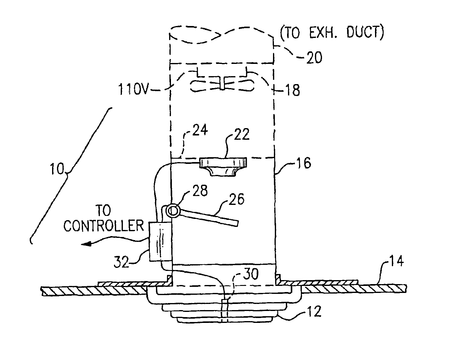
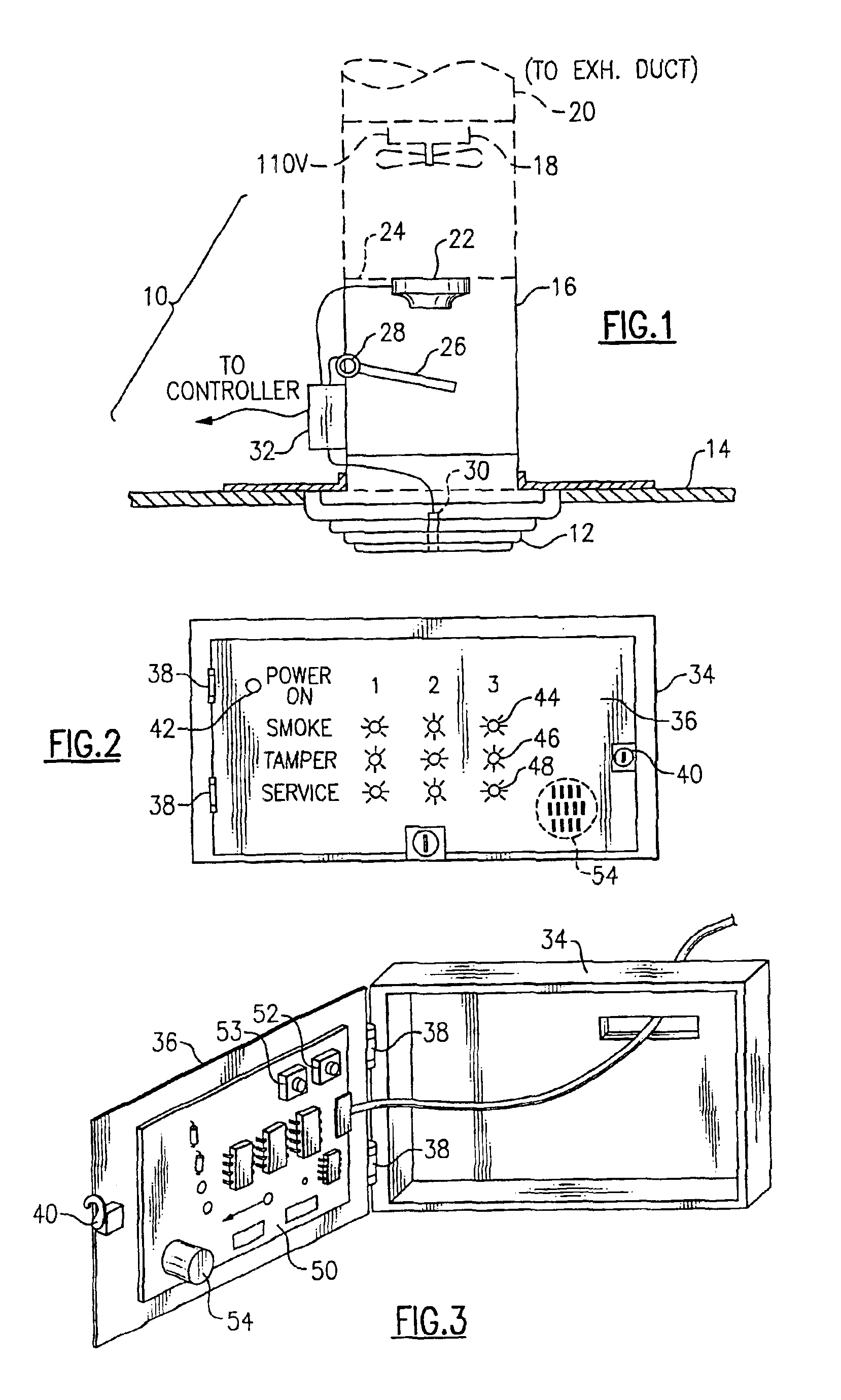
[0018]With reference to the Drawing, and initially to FIG. 1 thereof, smoke detection unit 10 in this embodiment is adapted to be mounted in the ceiling of a room, and has a front grille 12 (here, a ceiling grille) that is supported in a frame 14. In this case, the frame may be a two-foot by two-foot square matching the footprint of a standard ceiling tile, so that it may be fitted into a tile aperture in the gridwork of a standard drop ceiling. Above the grille 12 a duct 16 extends upward. Here the duct 16 may be a tubular duct of six-inch diameter, but the dimensions are not critical. In one option, a small, low-volume fan 18 is mounted at an upper end of the duct 16, and simply moves air from the zone, i.e., the room below the ceiling, into the space above the ceiling, where it circulates back into the room. In another option, a conduit 20 continues to attach with the exhaust ductwork of the building ventilation system. In either case, a flow of air is induced upwards through the...


PUM


Abstract

A smoke detection and monitoring arrangement detects surreptitious smoking in various zones in a building, e.g., rest rooms and break rooms, and also detects tampering. Each detection unit has an intake grille leading to a duct which contains an air flow detector, a smoke detector and an optical intrusion or tampering detector. Air flow may be induced by an internal fan, or may result from an optional connection to ventilation ductwork. Air flow, smoke, and tamper signals are fed from each unit to a central control panel, which may include visible indicators and an audible alarm.

Description

BACKGROUND OF THE INVENTION[0001]This invention relates to smoke detection and alarm systems, and is more specifically directed to a system for detecting presence of smoke, such as tobacco smoke, in one or more zones within a building structure. The invention is also directed to systems that detect and alert to attempts to block air flow through the detection unit or to defeat the detection of smoking.[0002]The invention is more particularly directed to a technique for detecting smoke in a confined area, such as a meeting room, bathroom, or conference room, for the purpose of enforcing indoor clean air laws and regulations.[0003]Because of concern for the health of workers and customers, many businesses, government offices, and other organizations have taken steps to limit smoking, and thus avoid exposing persons within their offices to second-hand smoke. This concern has also resulted recent government legislation and regulation to promote clean, healthy indoor air, for example, th...

Claims


Application Information

Patent Timeline
Patent Type & Authority Patents(United States)
IPC IPC(8): G08B17/10G08B13/19G08B19/00
CPCG08B13/19G08B17/10G08B19/005G08B17/113
Inventor DEACY, DAN
Owner DEACY DAN
Learn More