
Ultrasonic lead screw motor

a lead screw motor and ultrasonic technology, applied in the direction of instruments, device details, piezoelectric/electrostrictive device details, etc., can solve the problems of slipping, loud noise and vibration, and fast jaw movement to overcome the friction of clamping

Inactive Publication Date: 2005-09-06
NEW SCALE TECH
View PDF8 Cites 249 Cited by
  • Summary
  • Abstract
  • Description
  • Claims
  • Application Information

AI Technical Summary

Benefits of technology

"The invention is a device that can make a threaded shaft rotate and move back and forth at the same time. This happens by using ultrasonic vibrations on the nut that is connected to the shaft. The device also applies a force in the axial direction (the direction the shaft is pushed or pulled) on the shaft."

Problems solved by technology

This stepping linear actuator operates at frequencies from DC to several kilohertz, which produces loud noise and vibration.
Fast jaw movements overcome the clamping friction and create slippage.
This stick-slip motor makes similar noise and vibration as the above stepping motor but moves 100 times slower and holds position when power is turned off.
Generally ultrasonic motors are difficult to stop and start which limits precision.
However, even when such elements 16a′ / 16d′ and 16b′ / 16c′ are not activated simultaneously, there is a waste of energy.
The inactive pair of elements still are contiguous with the threads on screw rod 2 and, thus, cause drag friction.
This drag friction is a problem with the device of U.S. Pat. No. 6,147,435.

Method used


Image

  • Ultrasonic lead screw motor
  • Ultrasonic lead screw motor
  • Ultrasonic lead screw motor

Examples


Embodiment Construction

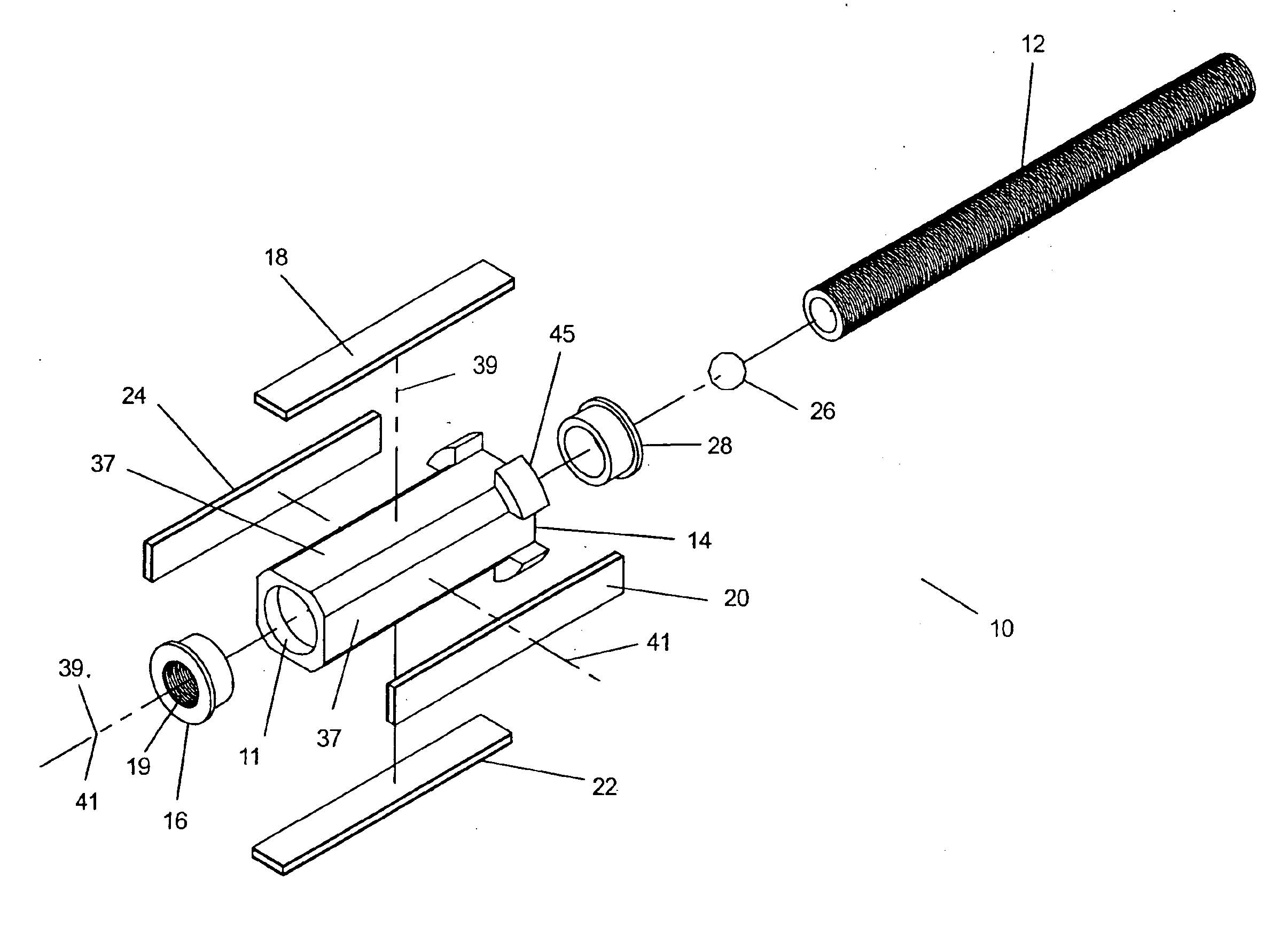
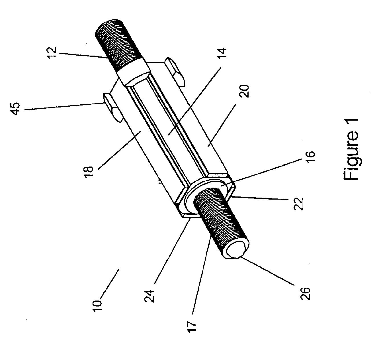
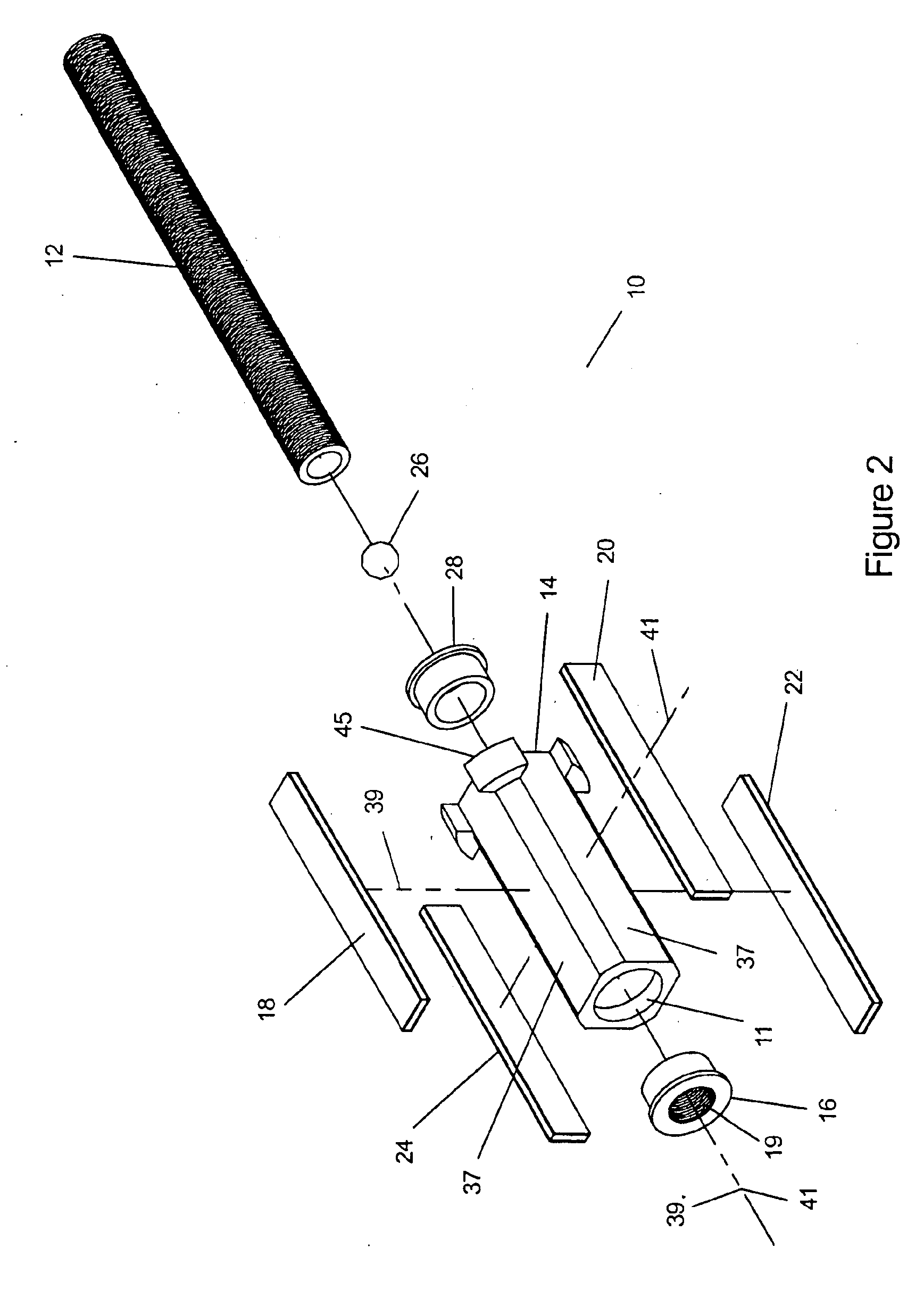
[0030]In one embodiment of this invention, a miniature ultrasonic linear motor rotates a lead screw to produce linear movement. A cylinder supports a threaded nut with a first bending mode resonant frequency in the ultrasonic range. The cylinder and nut are excited at this resonant frequency by transducers that cause the nut to orbit at the end of the cylinder. The transducers may be piezoelectric, electrostrictive, electrostatic, electromagnetic or any device that can stimulate the resonant vibration. At least two transducers are required to simultaneously excite the orthogonal bending modes of the cylinder with a plus or minus 90-degree phase shift and create a circular orbit. A close-fitting threaded shaft is installed inside the nut. A resilient axial load is applied to the shaft through a low friction coupling. The nut orbits at its resonant frequency, and the shaft's inertia keeps it centered. The orbit of the nut generates torque that rotates the shaft and creates linear move...


PUM


Abstract

An apparatus for driving a threaded shaft assembly that contains a threaded shaft with an axis of rotation and, engaged therewith, a threaded nut. Subjecting the threaded nut to ultrasonic vibrations causes the threaded shaft to simultaneously rotate and translate in the axial direction. The threaded shaft is connected to a load that applies an axial force to the threaded shaft.

Description

FIELD OF THE INVENTION[0001]A miniature ultrasonic linear motor assembly comprised of a threaded shaft and, engaged, therewith, a nut.BACKGROUND OF THE INVENTION[0002]Transducers using piezoelectric electrostrictive, electrostatic, or electromagnetic technologies are very useful for precise positioning at the nanometer scale. In the case of a piezoelectric device, the ceramic is formed into a capacitor that changes shape when charged and discharged creating a force transducer or position actuator. When used as a position actuator, the shape change of the piezoelectric ceramic is approximately proportional to the applied voltage. Piezoelectric actuators are limited in range to about 0.1 percent of the length of the ceramic which corresponds to typical stroke lengths of tens of micrometers. While the high stiffness and nanometer precision of piezoelectric actuators is very useful, more stroke is needed for many applications.[0003]Numerous piezoelectric motor designs have been develope...

Claims


Application Information

Patent Timeline
Patent Type & Authority Patents(United States)
IPC IPC(8): H01L41/09A61M5/142H10N30/20A61M5/145H10N30/85G02B7/10H10N30/00H10N30/80
CPCG02B7/102H02N2/0095H02N2/02A61M5/14248A61M5/1452
Inventor HENDERSON, DAVID A.
Owner NEW SCALE TECH
Learn More