Screening apparatus with slot ring moveable in axial direction

Inactive Publication Date: 2005-09-06
VALMET FIBERTECH AKTIEBOLAG
View PDF21 Cites 8 Cited by
  • Summary
  • Abstract
  • Description
  • Claims
  • Application Information

AI Technical Summary

Benefits of technology

[0011]In accordance with the present invention, apparatus is provided for screening a fibrous suspension comprising a housing, a rotary screen mounted for rotation within the housing, the rotary screen including an upper end, a lower end, and a knob ring disposed at the lower end of the rotary screen, a screen chamber between the rotary screen and the housing including an inner surface defined by the rotary screen, an outer surface and a lower surface, an inlet for providing the fibrous suspension to the screen chamber, a reject outlet for withdrawing a reject portion of the fibrous suspension from the screen chamber, an accept outlet for withdrawing an accept portion of the fibrous suspension from the rotary screen, an outer screen chamber surface defining the outer surface of the screen chamber, a bottom screen chamber surface defining the lower surface of the screen chamber, a slot ring associated with the bottom screen chamber surface and adjacent to the knob ring defining a gap therebetween, and adjustment means for movably adjusting the location of the slot means whereby the size of the gap may be adjusted and the fibrous suspension may be substantially prevented from passing from the screen chamber through the gap, the adjustment means being at a location whereby the gap may be adjusted from outside of the housing. Preferably, the fibrous suspension comprises a pulp suspension.
[0015]In accordance with the present invention apparatus has been provided in which the measuring and adjusting of the gap width can be carried out much faster and considerably simpler than by processes known in the art. The gap width can thus be adjusted as often as it is required for always maintaining a desired gap width.
[0016]The slot ring of the present invention is movable in the axial direction in relation to the bottom portion by means of at least one gap adjustment device. Every gap adjustment device is located in the bottom portion, and can be operated from the outside of the screening apparatus. The gap width can thus be measured and adjusted without requiring the screening apparatus to be emptied of pulp suspension, cleaned and dismantled.
[0020]Another advantage obtained with the present invention is that when the screening apparatus comprises a support means it is possible to make at least a part of the support means exchangeable. This exchangeable part can then be utilized as a wearing part.

Problems solved by technology

When the screening apparatus is in operation, the knob ring and slot ring are subjected to wear.
In this manner, the gap increases in size, which results in greater amounts of accept passing through the gap, at the same time as the pumping effect deteriorates.
Measuring of the gap width is very tedious and troublesome.
In cases when the gap is found to be too great, high costs will also be involved for repairing, and alternatively exchanging parts, which requires additional time.
Due to the fact that it is so troublesome and expensive to change the gap width, the screen is kept in operation far too long, even if the gap width is greater than desirable.

Method used


Image

  • Screening apparatus with slot ring moveable in axial direction
  • Screening apparatus with slot ring moveable in axial direction
  • Screening apparatus with slot ring moveable in axial direction

Examples


Embodiment Construction

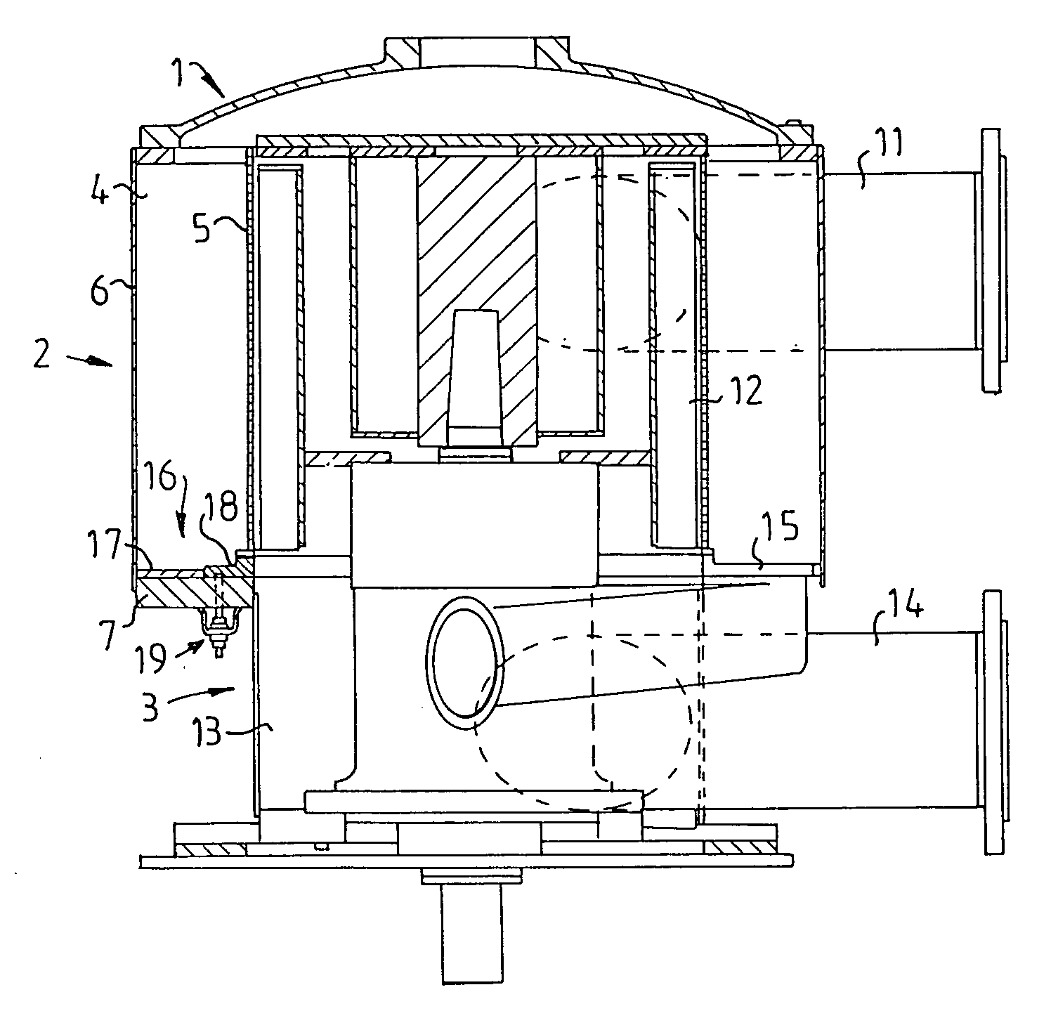
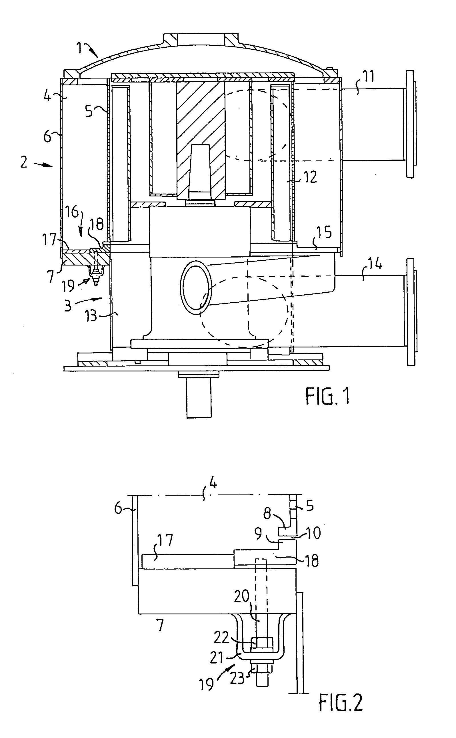
[0028]The screening apparatus shown in FIG. 1 comprises a pressurized screen housing 1 with an upper portion 2, the diameter of which is greater than the lower portion 3 of the screen housing 1. In the upper portion 2 of the screen housing a screen chamber 4 is located, which is defined inwardly by a rotationally symmetrical rotary tubular screen means 5, is defined outwardly by an outer defining surface 6, and is defined downwardly by a bottom portion 7, which has its lower side on the outside of the screening apparatus.

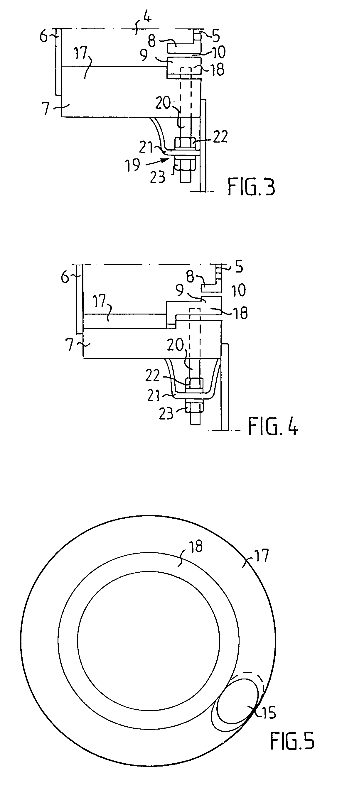
[0029]Between a knob ring 8 located on the lowermost portion of the screen means 5 and a slot ring 9, a gap 10 is formed.

[0030]The fibrous suspension to be separated, which in this case is a pulp suspension, is introduced by means of an inlet 11 in the upper portion 2 of the screen housing 1 to the screen chamber 4. The accepted fraction (the accept) of the pulp suspension flows through the rotating screen means 5 and into an accept chamber 12. The accept flows ther...


PUM

PropertyMeasurementUnit
Sizeaaaaaaaaaa

Abstract

Apparatus for screening pulp suspensions is provided, including a housing, a rotary screen within the housing, a screen chamber between the rotary screen and the housing, a reject outlet, an accept outlet, an outer screen surface defining the outer surface of the screen chamber, a bottom screen surface defining the lower surface of the screen chamber, a slot ring at the bottom screen surface and adjacent to a knob ring at the lower end of the rotary screen, and an adjustment screw for adjusting the size of the gap between the knob ring and the slot ring from outside of the housing.

Description

FIELD OF THE INVENTION[0001]The present invention relates to a screening apparatus for separating fibrous suspensions, preferably pulp suspensions. The screening apparatus comprises a screen housing with a screen chamber, which is defined inwardly by a rotary tubular screen, outwardly by an outer defining surface, and downwardly by a bottom portion. Lowermost on the screen means a knob ring is located. Between the knob ring and a slot ring a gap is formed. The screening apparatus further comprises an inlet for fibrous suspension to the screening apparatus, a reject outlet for reject from the screen chamber and an accept outlet for accept from the screening apparatus.BACKGROUND OF THE INVENTION[0002]Screening apparatus of the above type is used during both coarse and fine screening of pulp suspensions, preferably for fractionating or separating impurities and other foreign matter which is not desired to be included in the final product, such as shives, knots, coarse particles, scrap,...

Claims


Application Information

Patent Timeline
IPC IPC(8): D21D5/06D21D5/00D21D5/02B03B5/00
CPCD21D5/06
Inventor KRISTROM, KLASFORSLUND, KJELL
Owner VALMET FIBERTECH AKTIEBOLAG
Why Eureka
Try Eureka