Method of connecting raceways with or without a fitting base
a technology of fitting base and raceway, applied in the direction of rod connection, coupling, branching pipe, etc., can solve the problems of inefficiency and increase costs, and achieve the effect of cost-effective and efficient us
- Summary
- Abstract
- Description
- Claims
- Application Information
AI Technical Summary
Benefits of technology
Problems solved by technology
Method used
Image
Examples
first embodiment
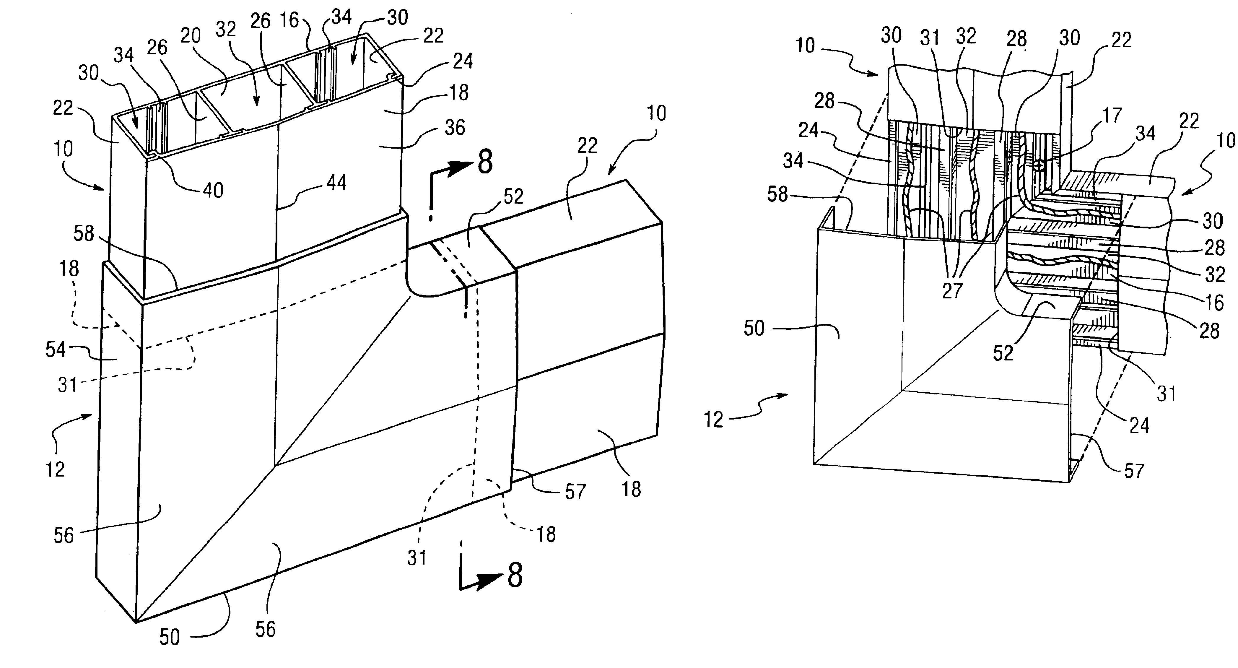
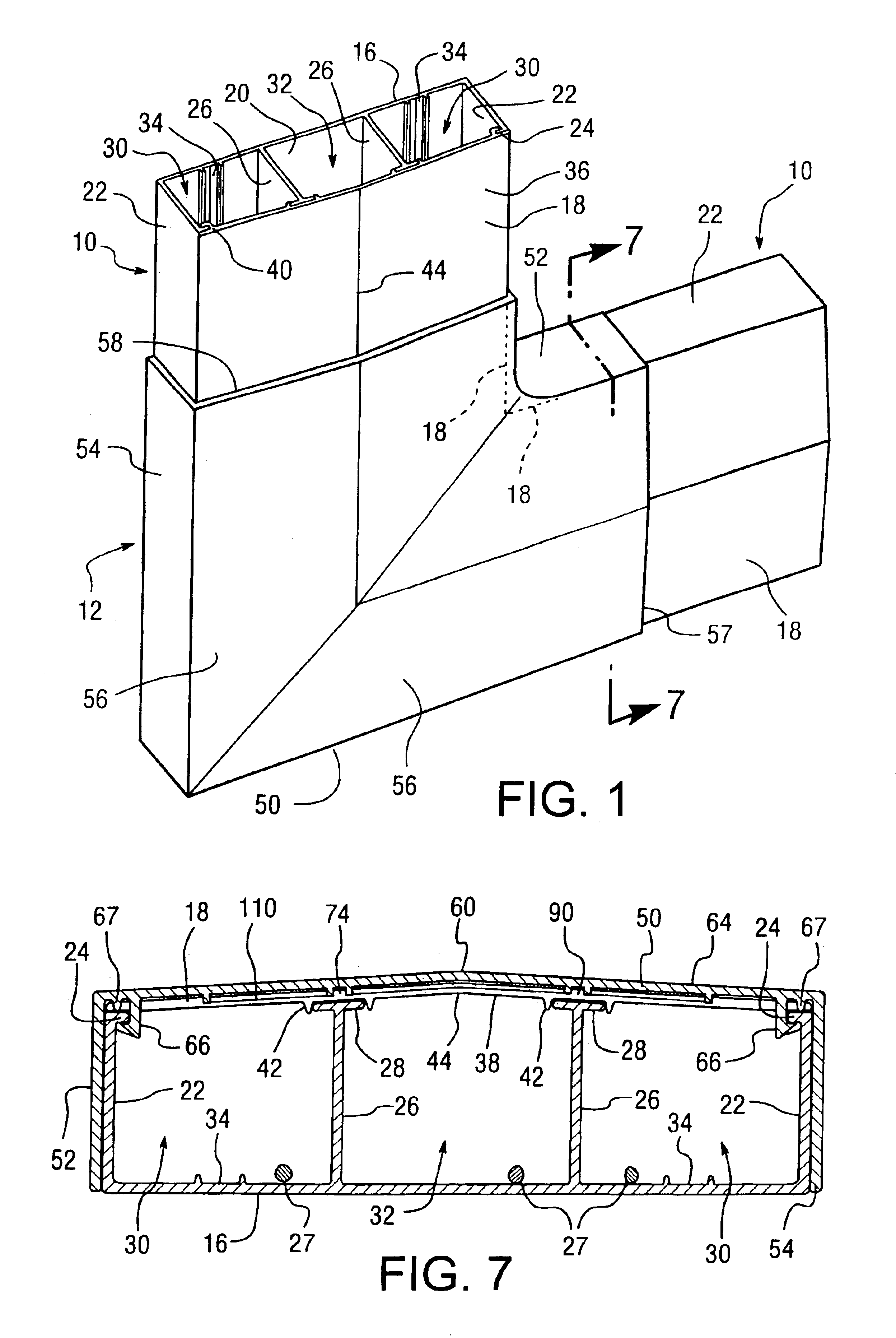
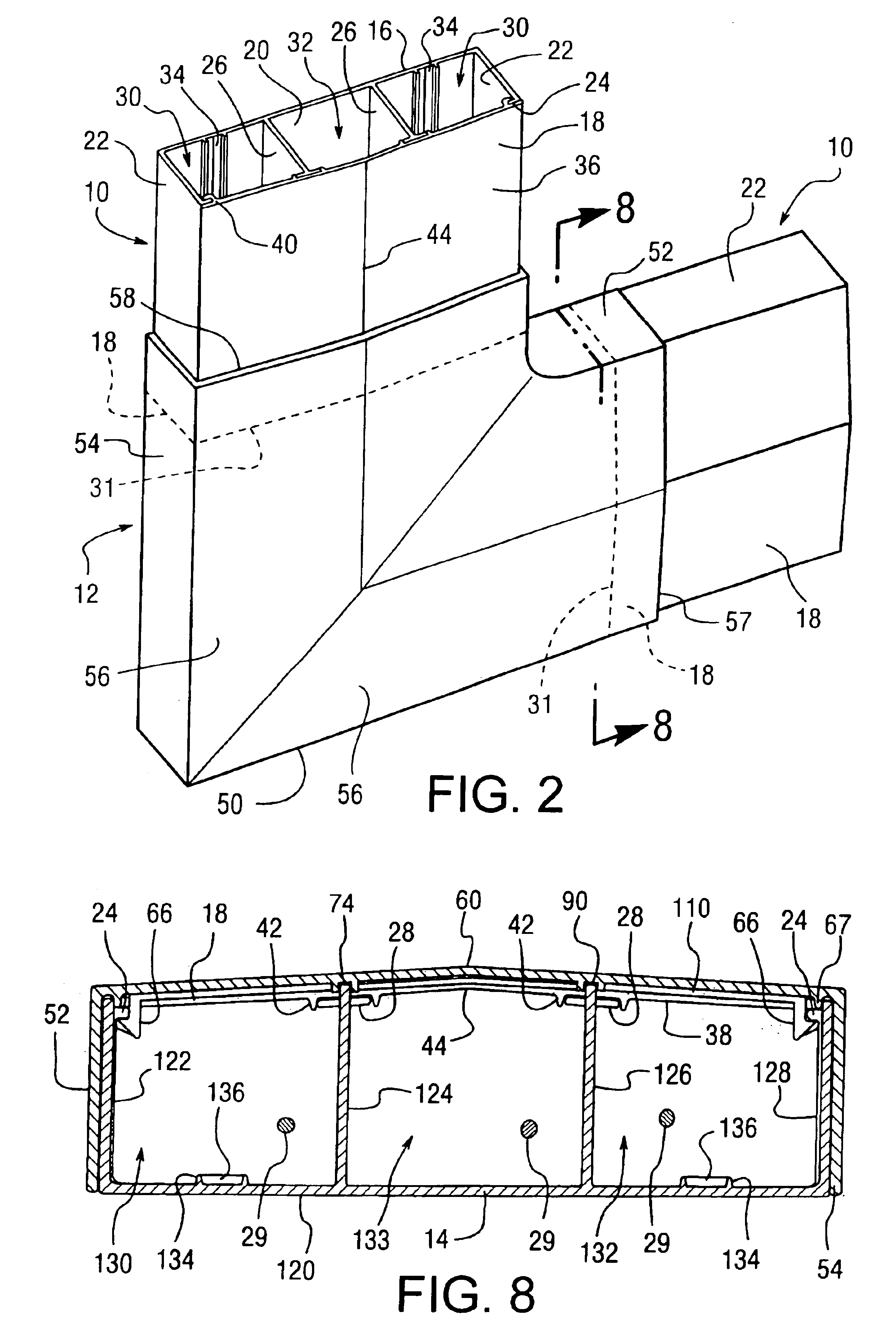
[0032]Referring to FIGS. 1-8, a flat elbow or cover fitting 12, according to the present invention, includes a top 50 and first and second opposing sides 52 and 54 extending from and being substantially perpendicular with cover fitting 12. In particular, top 50 has two sections 56 connected at joint 59 having inner and outer surfaces 62 and 64 forming a substantial L-shape with first side 52 extending from the inner portion of the L and opposing second side extending along the outer portion of the L. Each section 56 further includes a central bend 60 that matches a bend 44 formed in raceway cover 18 allowing first and second ends 57 and 58 of each section 56, respectively, to accommodate raceway 10. A pair of hooks or securing members 66 extend from inner surface 62 and are disposed proximate first and second sides 52 and 54 at first and second ends 57 and 58 for engaging raceway 10, as best seen in FIG. 6.
[0033]Cover fitting 12 also includes first and second curved walls 68 and 70 ...
second embodiment
[0044]Referring to FIGS. 9-11, an internal elbow or cover fitting 138, according to the present invention, includes a top 140 (see FIG. 11) and first and second opposing sides 144 and 146 extending from opposing ends of cover fitting 138, similar to cover fitting 12. However, unlike top 50 of cover fitting 12, top 140 is formed of one section having a convex inner surface 148 and a concave outer surface 150. First and second sides 144 and 146 extend from inner surface 148 and are curved to match the curvature of top 140. This allows cover-fitting 138 to connect two raceways 10 when they converge to a corner forming an acute angle 162 therebetween, since the curvature of top 140 and first and second sides 144 and 146 corresponds to the acute angle 162, as best seen in FIGS. 9 and 10, such that top 140 covers each raceway base 16 and first and second sides 144 and 146 overlap the sidewalls 22 of each raceway base 16.
[0045]As with cover fitting 12, cover-fitting 138 has hooks that enga...
third embodiment
[0050]Referring to FIGS. 12-14, an external elbow or cover fitting 200, according to the present invention, which like cover fitting 12 and cover fitting 138, includes a top 202 and first and second opposing sides 204 and 206 extending from opposing ends of cover fitting 200, as best seen in FIG. 14.
[0051]Top 202 is formed of two sections 208 with each section having a first flat portion 210, a second ramp portion 212, and a third larger ramp portion 214. A flat central portion 216 connects the two sections 208 forming a substantially V-shaped top 202 wherein the inner surface 218 forms the inner portion of the V and the outer surface 219 forms the outer portion of the V, as best seen in FIG. 14. First and second sides 204 and 206 extend from inner surface 218 and are similarly V-shaped. This allows cover-fitting 200 to connect two raceways 10 when they converge to a corner forming an obtuse angle 220 therebetween, since the V-shape of top 202 matches obtuse angle 220, as best seen ...
PUM
| Property | Measurement | Unit |
|---|---|---|
| bend radii | aaaaa | aaaaa |
| area | aaaaa | aaaaa |
| bend radius | aaaaa | aaaaa |
Abstract
Description
Claims
Application Information
 - R&D
- Intellectual Property
- Life Sciences
- Materials
- Tech Scout
- Unparalleled Data Quality
- Higher Quality Content
- 60% Fewer Hallucinations
Browse by: Latest US Patents, China's latest patents, Technical Efficacy Thesaurus, Application Domain, Technology Topic, Popular Technical Reports.
© 2025 PatSnap. All rights reserved.Legal|Privacy policy|Modern Slavery Act Transparency Statement|Sitemap|About US| Contact US: help@patsnap.com


