Image read-out method and apparatus

Inactive Publication Date: 2005-08-30
FUJIFILM CORP +1
View PDF16 Cites 10 Cited by
  • Summary
  • Abstract
  • Description
  • Claims
  • Application Information

AI Technical Summary

Benefits of technology

[0020]The primary object of the present invention is to provide an image read-out method, which is capable of being utilized commonly in an autoradiography image detecting system, a chemiluminescence image detecting system, an electron microscope image detecting system, a radiation diffraction image detecting system, a fluorescence image detecting system, and the like, and which is capable of yielding an image signal representing an image having good image quality and with a high sensitivity.
[0025]iii) irradiating the stimulating ray beam, which has been produced by the stimulating ray source, onto the image carrier, which has been supported on the stage, by use of an optical head, the stimulating ray beam causing the image carrier to emit light carrying information of the image carried on the image carrier,
[0055]With the image read-out method and apparatus in accordance with the present invention, wherein the optical head comprises the concave mirror and the lens, the advantages over the use of an optical head consisting of a plane mirror and a lens are capable of being obtained in that the position of the beam waist of the stimulating ray beam is capable of being set at a position close to the surface of the image carrier, and the sharpness of the obtained image is thus capable of being enhanced, and in that the light emitted by the image carrier is capable of being collected efficiently. With the optical head consisting of the plane mirror and the lens, the problems occur in that, in cases where the position of the image carrier and the position of the focal point of the lens are shifted from each other, the light emitted by the image carrier cannot be formed into a collimated light beam or a converged light beam only with the refracting power of the lens and impinges in the divergent state upon the plane mirror, and therefore the light having been reflected from the plane mirror travels in a more divergent state. However, with the image read-out method and apparatus in accordance with the present invention, wherein the optical head comprises the concave mirror and the lens, the emitted light incident in a divergent state is capable of being converged, and therefore the light emitted by the image carrier is capable of being guided efficiently toward the photo detecting means. Also, since the light collecting efficiency is thus capable of being enhanced, the image read-out operation is capable of being performed with a high sensitivity.

Problems solved by technology

In such cases, the light emitted by the image carrier cannot be sufficiently collected and guided to the photodetector, and therefore the sensitivity of the image read-out apparatus cannot be kept high.

Method used


Image

  • Image read-out method and apparatus
  • Image read-out method and apparatus
  • Image read-out method and apparatus

Examples


Embodiment Construction

[0060]The present invention will hereinbelow be described in further detail with reference to the accompanying drawings.

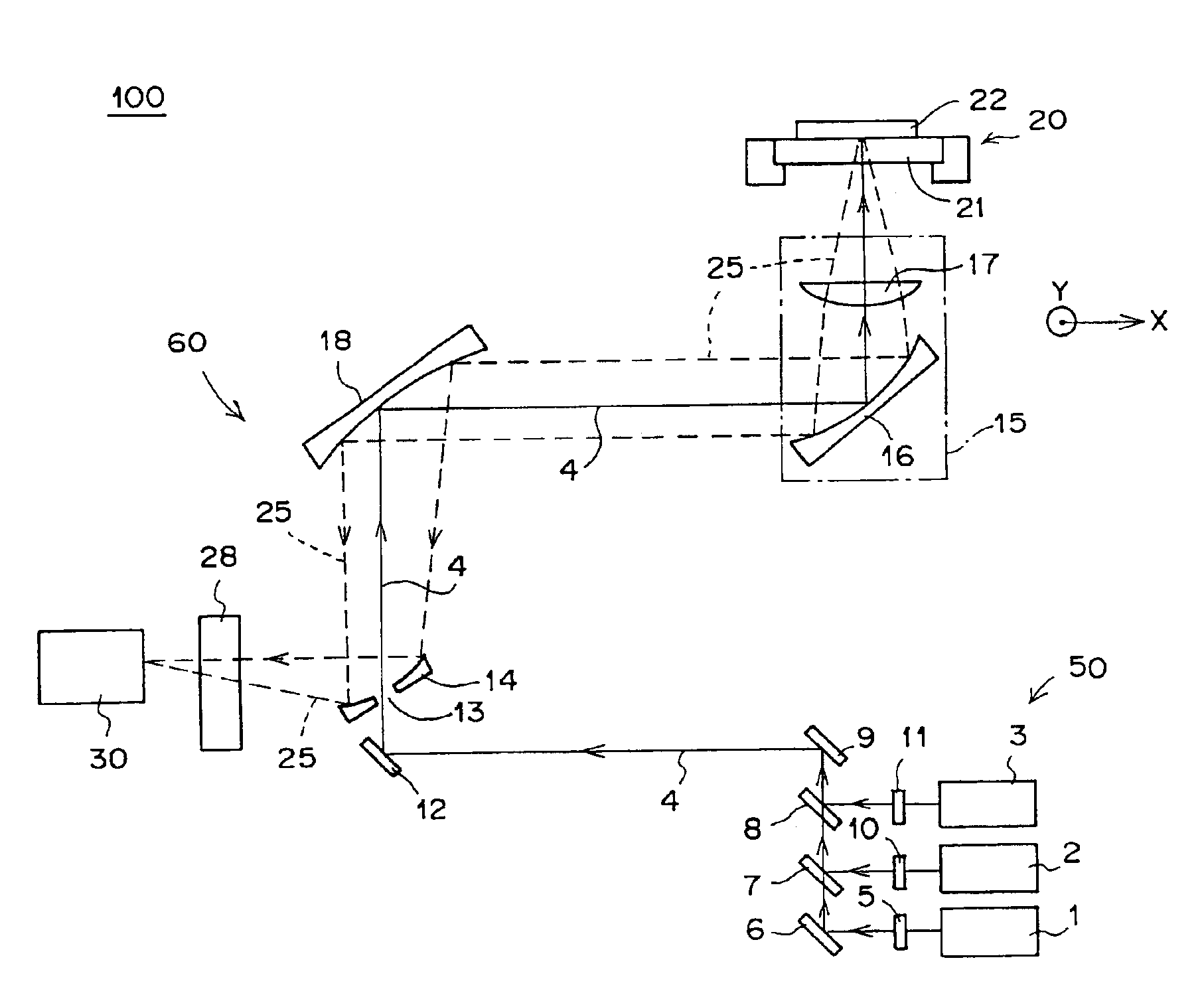
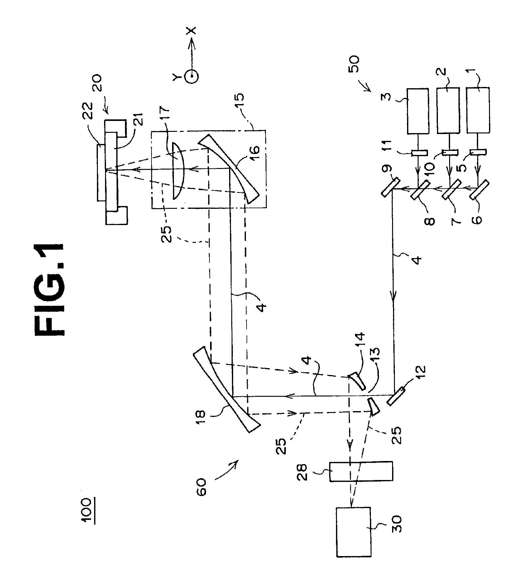
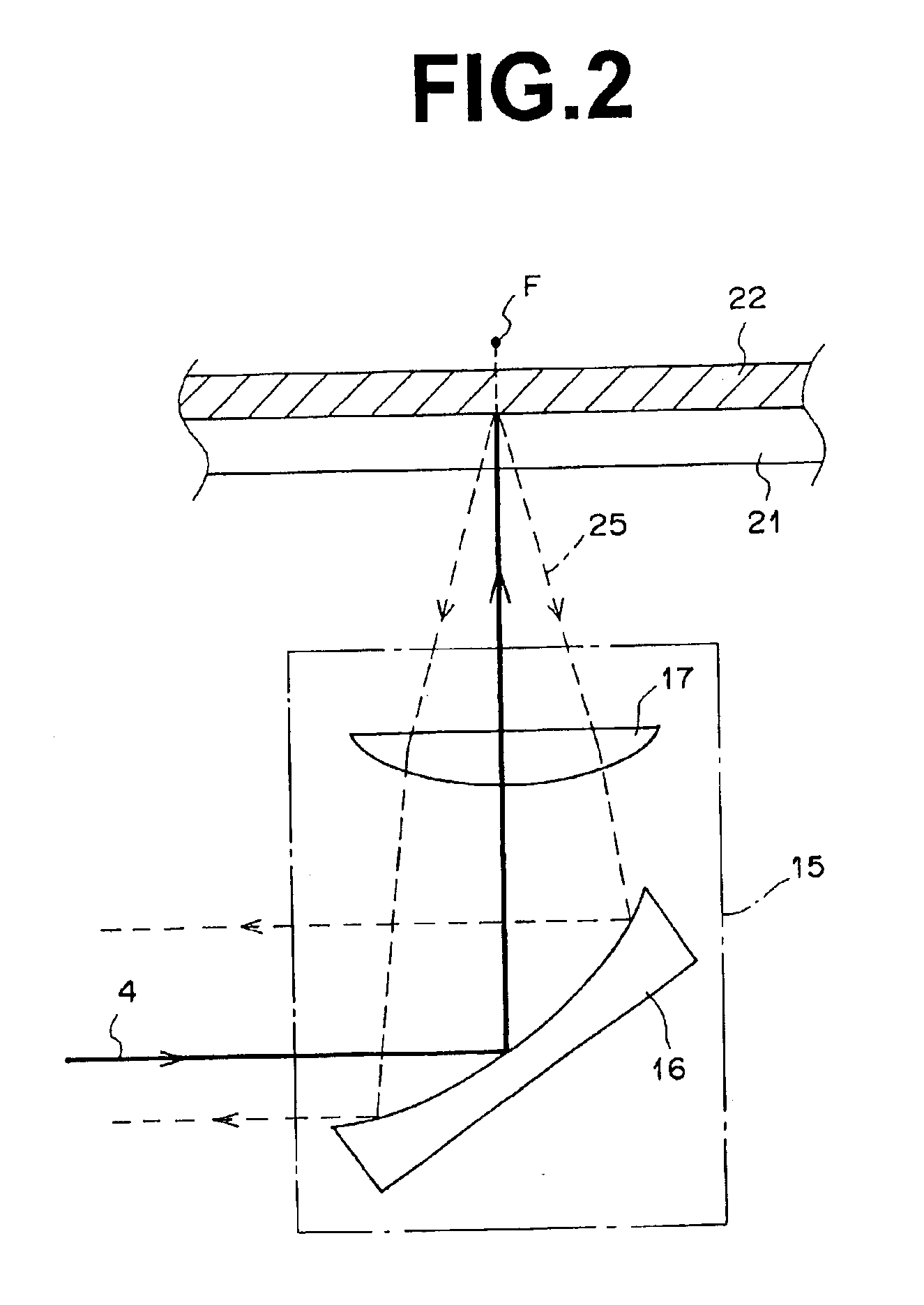
[0061]FIG. 1 is an explanatory view showing an embodiment of the image read-out apparatus in accordance with the present invention. FIG. 2 is an enlarged side sectional view showing a constitution in the vicinity of an optical head in the embodiment of FIG. 1. FIG. 3 is an enlarged schematic perspective view showing a constitution in the vicinity of a photomultiplier in the embodiment of FIG. 1.

[0062]With reference to FIG. 1, an image read-out apparatus 100, which is an embodiment of the image read-out apparatus in accordance with the present invention, comprises a stage 20 provided with a glass base plate 21, on which an image carrier 22 carrying an image thereon is supported. The image read-out apparatus 100 also comprises an optical head 15 for irradiating a laser beam 4, which act as stimulating rays, onto the image carrier 22. The laser beam 4 acting as the st...


PUM


Abstract

With an optical head, a stimulating ray beam produced by a stimulating ray source is irradiated onto an image carrier supported on a stage, and light emitted by the image carrier is collected and guided toward a photodetector. At least either one of the optical head and the stage is moved with respect to the other and in two-dimensional directions along a plane parallel with the other. The optical head comprises a concave mirror for reflecting the stimulating ray beam, which travels in parallel with the stage, toward the image carrier, and a lens for converging the stimulating ray beam, which has been reflected from the concave mirror, onto the image carrier. The lens and the concave mirror also guide the light, which is emitted by the image carrier, toward the photodetector.

Description

BACKGROUND OF THE INVENTION[0001]1. Field of the Invention[0002]This invention relates to an image read-out method and apparatus, which are capable of being utilized commonly in an autoradiography image detecting system, a chemiluminescence image detecting system, an electron microscope image detecting system, a radiation diffraction image detecting system, and a fluorescence image detecting system.[0003]2. Description of the Related Art[0004]It has been proposed to use stimulable phosphors as radiation detecting materials in radiation image diagnosing systems. Specifically, energy from radiation carrying image information of an object is stored and recorded on a stimulable phosphor, which is contained in a stimulable phosphor layer of a stimulable phosphor sheet. The stimulable phosphor layer of the stimulable phosphor sheet, on which the radiation image information has been stored, is then exposed to an electromagnetic wave acting as stimulating rays, which cause the stimulable ph...

Claims


Application Information

Patent Timeline
IPC IPC(8): G01N33/53G01N21/64G01N33/566G02B17/08G03B42/02H01S3/08H04N5/30H04N5/32H04N1/04G01N21/76
CPCG01N21/6456G01N21/76G01N2021/6419
Inventor NISHIOKA, YUKINORI
Owner FUJIFILM CORP
Why Eureka
Try Eureka