Method for generating small bubbles for a smoke-filled air stream

a technology of smoke-filled air and small bubbles, which is applied in the field of water pipes, can solve the problems of undesirable components and typically unhealthy balance, and achieve the effect of reducing desired performance and short li

Inactive Publication Date: 2005-08-30
PHX GLASS
View PDF2 Cites 12 Cited by
  • Summary
  • Abstract
  • Description
  • Claims
  • Application Information

AI Technical Summary

Benefits of technology

[0009]The inventors have found that reducing the average inside diameter of the bubbles to about 2 millimeters or less in one or more water stage upstream of a user dramatically reduces the emerging gas temperature and removes substantially more of undesirable smoke components that prior art devices. However, making small bubbles in a smoke filled gas stream has an important cost.
[0011]The present inventors attempted replacing the holes in the end of the glass or metal tube in a water pipe with a sintered “stone” used in aquariums to generate small bubbles. The device worked well to make small bubbles but had a very short life. The small passages of the stone plugged and could not be cleaned. The present inventors then experimented with several alternate structures to arrive at the first embodiment of the invention. The first embodiment accelerates a smoke filled gas stream to impinge on an underside of a top cap and then down from the top cap to small accelerator openings that emit the smoke filled gas as small bubbles into a volume of water. The pressure drop of the gas across the accelerator openings that is substantially greater than the pressure drop through the water the bubbles encounter on the water stage. This means a user may tilt the invention water stage to 45 degrees or more with little, if any, reduction in desired performance.

Problems solved by technology

Excluding the desirable components, the balance of the components are undesirable and typically unhealthy.

Method used


Image

  • Method for generating small bubbles for a smoke-filled air stream
  • Method for generating small bubbles for a smoke-filled air stream
  • Method for generating small bubbles for a smoke-filled air stream

Examples


first embodiment

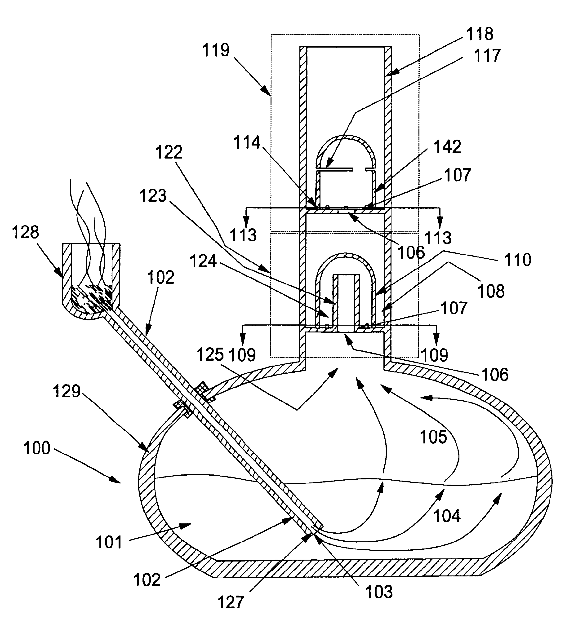
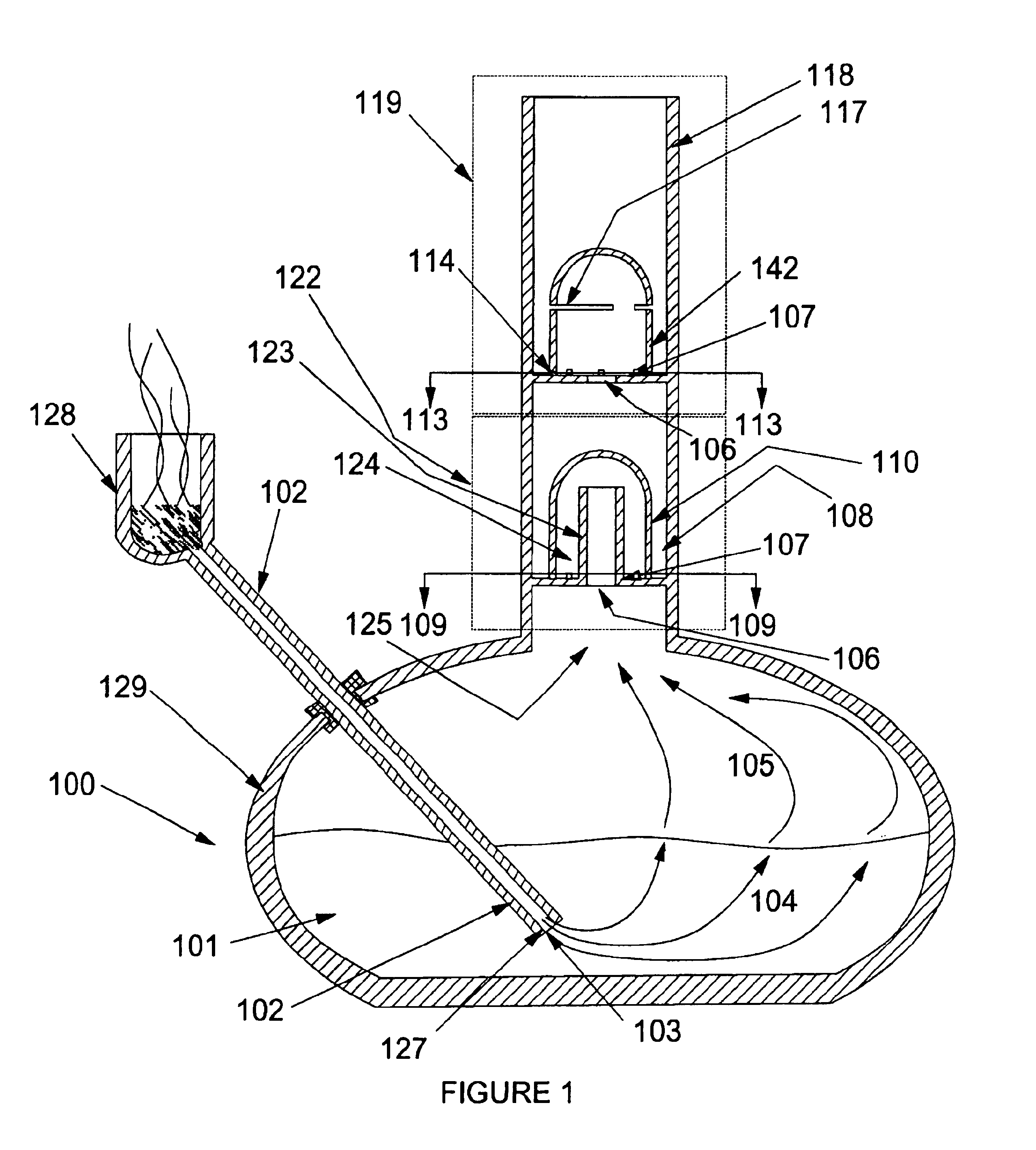
[0029]With reference to FIGS. 1-5, stage 109 comprises a portion of housing 118 and its central bore. To an inside wall of the central bore is sealed floor plate 107. Plate 107 defines an opening 106, from which extends upward a tube 123 that ends in opening 132. A preferred inside diameter of tube 123 is from about 5 to about 20 millimeters and a more preferred inside diameter is from about 10 to 14 millimeters. Enclosing tube 123 is a structure comprising a top cap 133 extending down to side walls 110, at whose base are located small accelerator holes 157. Holes 157 in a first embodiment are rectangular extending from a top of floor 107 up to a height of from about 0.5 to about 4.5 millimeters and a width of from about 0.5 to 5.5 millimeters with a hydraulic cross section area of about from 1-10 square millimeters, and more preferably from about 2-4 square millimeters.

[0030]An inside surface of housing 118 and an outside surface of walls 110 define annular space 108. An inside sur...

second embodiment

[0034]FIGS. 7-9 are the invention. FIG. 7 shows that a floor 112 seals to the inside surface of the largest bore of housing 118. Floor 112 defines opening 111 that opens to a space 145 defined by cap 146 (similar in structure and function to cap 133) and walls 142. Openings 114 communicate between space 145 and annular space 153 between the inside walls of the largest bore of housing 118 and the outside surface of walls 142. Slots 117 are formed about an inch or more below the top of cap 146 and at about a transition from walls 142 to cap 146 and are supported at sections 148 (shown in FIG. 8). The operation of the demister is shown in FIG. 7. Water droplets are carried up by a third smoke filled gas stream 150 through opening 111 into space 145. Droplets 152 impinge on an underside of cap 146, adhere thereon and drain down walls 142 to opening 111 where water flow 143 drains to a water stage below. Droplets 160 are drawn through slots 117 and impinge on the inside walls of the larg...


PUM


Abstract

The present invention is a small bubble generator in a water stage cleaning and cooling a smoke filled air stream. A demister is a second embodiment of the invention to remove entrained water droplets from a cleaned and cooled smoke filled air stream issuing from the water stage.

Description

[0001]This application claims the benefit of Ser. No. 60 / 360,319 filed Feb. 28, 2002.BACKGROUND OF THE INVENTION[0002]The present invention relates to water pipes using more than a single stage of water to condition smoke before it reaches the user's mouth.[0003]U.S. Pat. No. 4,357,948 shows a water pipe with a device located in a tube above a bottom water reservoir. The device can only form large and non-uniform bubbles from smoke filled air passing through water retained in the device. The device loses almost all effectiveness when tilting it more than a few degrees from vertical, as a relatively low water head at one side of the tube allows all the smoke filled air to escape through the water at the point where the depth is smallest.SUMMARY OF THE INVENTION[0004]A first embodiment of the invention is a small bubble generator system for smoke filled air generated from in a pipe and drawn by vacuum force of human lungs through a water stage. The first embodiment preferably processe...

Claims


Application Information

Patent Timeline
Patent Type & Authority Patents(United States)
IPC IPC(8): A24F1/00A24F1/30
CPCA24F1/30
Inventor CARSTENS, CHRISTOPHERCARSTENS, DANIEL
Owner PHX GLASS
Why Eureka
Try Eureka