
Quantification method and system for corrosion and damage assessment

Inactive Publication Date: 2005-08-23
THE BOEING CO
View PDF39 Cites 8 Cited by
  • Summary
  • Abstract
  • Description
  • Claims
  • Application Information

AI Technical Summary

Benefits of technology

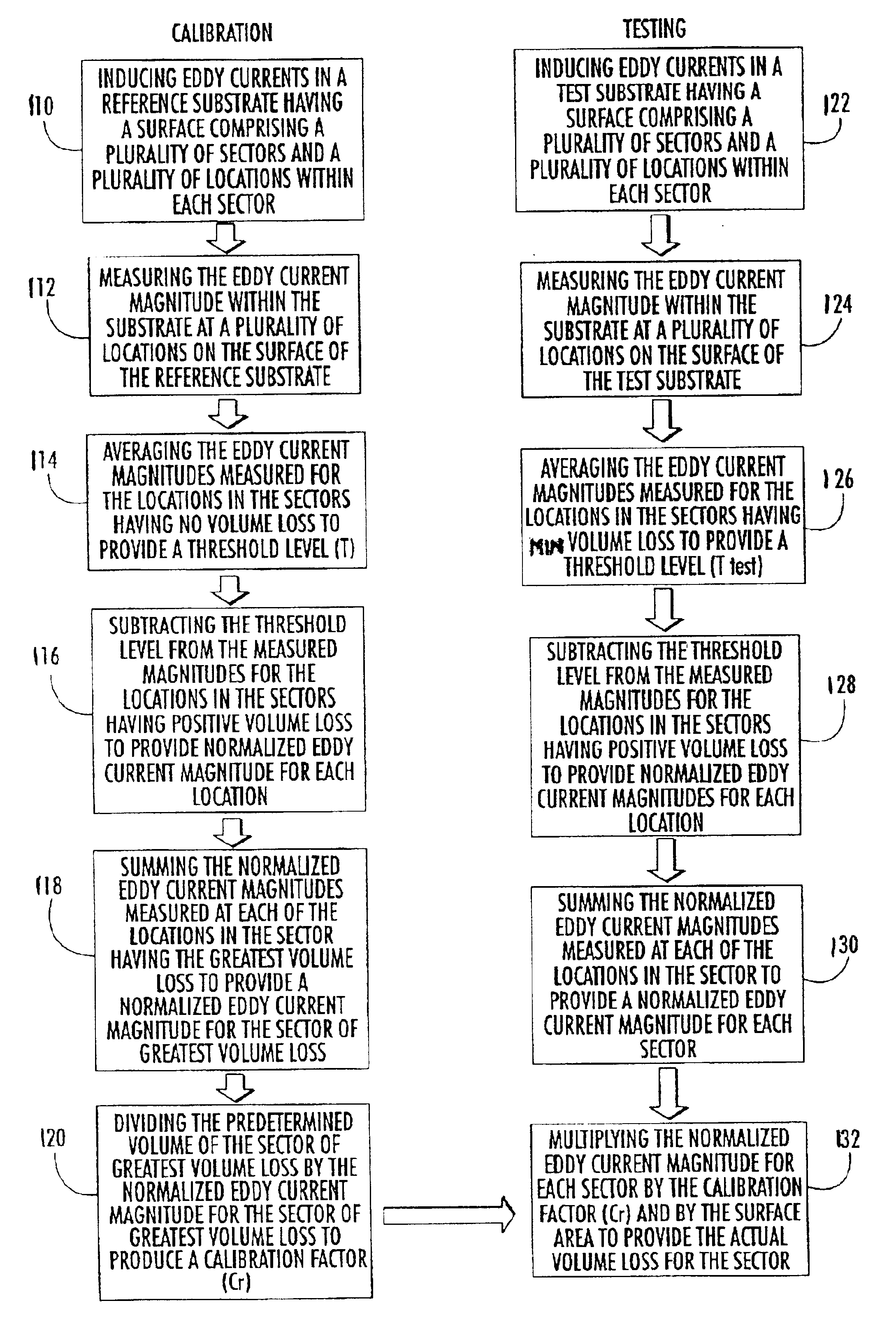
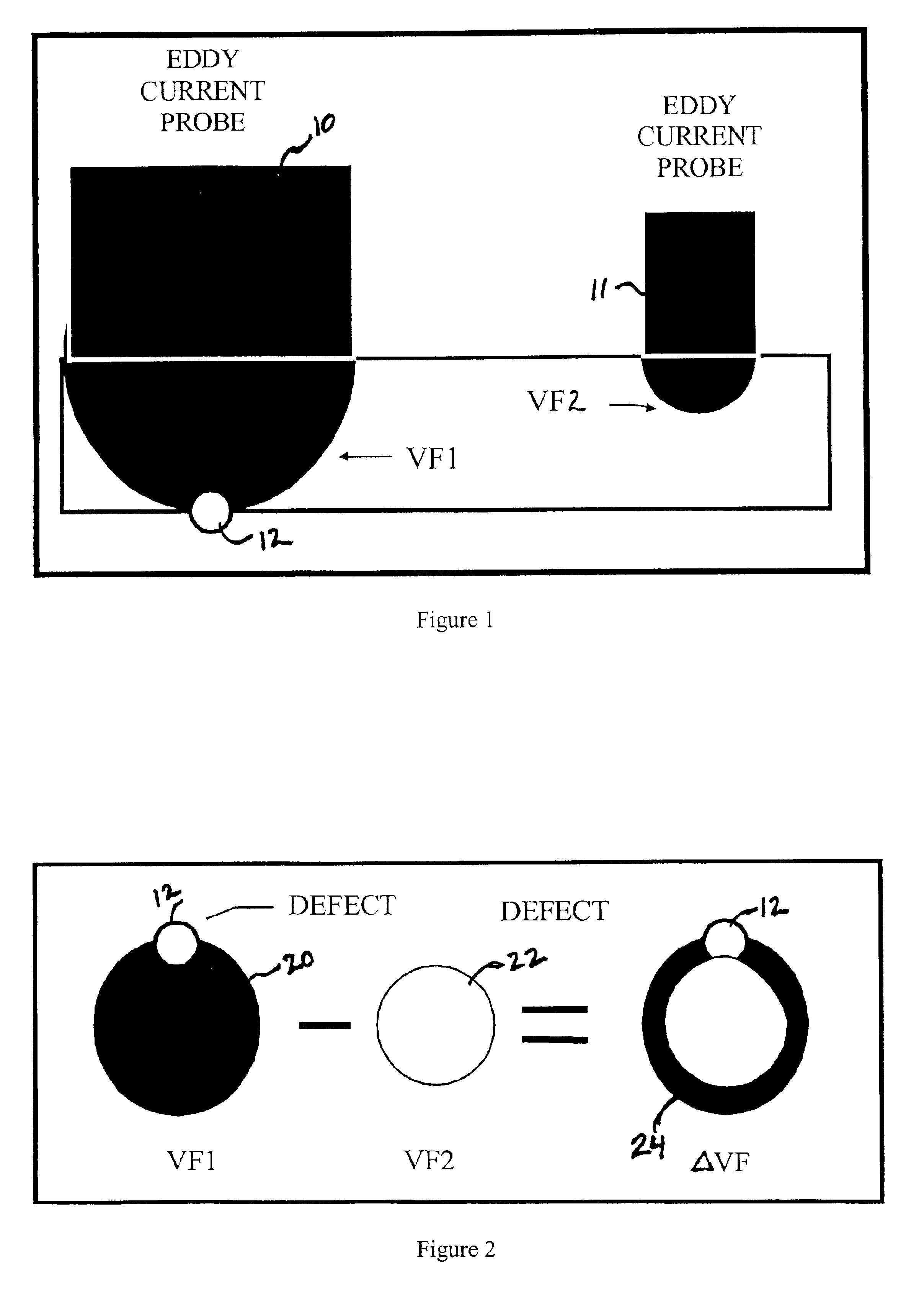
[0010]According to one embodiment, the present invention provides a method for the direct measurement and quantification of the volume loss along the surface and sub-surface of a substrate and thus more accurately depicts the surface and sub-surface profile of a substrate than conventional processes which can only provide comparative measurements of a surface profile or two dimensional anomalies on a test surface. In addition, the method of the invention can be used with various types of materials and can be used to measure volume losses even on non-planar surfaces such as around fasteners or inside fastener holes where corrosion defects often originate. The method of the invention allows a contour or three-dimensional map of the surface of substrate to be produced illustrating the material lost due to corrosion or damage. Even more advantageously, the method of the invention allows for the early determination of metal loss due to corrosion and damage thereby allowing replacement or repair of the test substrate prior to failure of the substrate.

Problems solved by technology

Corrosion damage is a significant threat to the safe operation of both military and commercial aircraft.
Failure to detect and correctly quantify corrosion damage can lead to failure of various aircraft components.
Corrosion damage is an even more significant problem with military aircraft due to the extreme environments in which they must operate.
However, this technique is limited to flat surfaces and only presents images that are visually compared with surrounding areas.
The technique is limited by the inability to produce corrosion reference standards with quantifiable defects.
As a result, assessment of corrosion damage in an aircraft metallic structure has required a complete understanding of the physics involved and extensive experience of a specialist in complex and time consuming inspection techniques currently available in the industry.
In other words, corrosion damage determination has been highly subjective and quality depends to a large degree upon the individual conducting the evaluation.
The great majority of damage to structural members due to corrosion originates from corrosion damage within the fastener holes and beneath the surface at faying surfaces.

Method used


Image

  • Quantification method and system for corrosion and damage assessment
  • Quantification method and system for corrosion and damage assessment
  • Quantification method and system for corrosion and damage assessment

Examples


Embodiment Construction

[0026]The present invention will be described more fully hereinafter with reference to the accompanying drawings, in which preferred embodiments of the invention are shown. This invention can, however, be embodied in many different forms and should not be construed as limited to the embodiments set forth herein; rather, these embodiments are provided so that this disclosure will be thorough and complete, and will fully convey the scope of the invention to those skilled in the art.

[0027]The present invention overcomes the problems associated with detecting and evaluating corrosion that is deeper than 0.100 inch from the inspection surface. The limitations associated with conventional eddy current inspection systems are obviated by the methods and apparatuses of the present invention. Known eddy current corrosion detection systems are unable to detect sub-surface corrosion because the eddy current field being used cannot penetrate into the material being inspected. Deeper penetration ...


PUM


Abstract

The present invention provides a method for the direct measurement and quantification of the material volume loss on and beneath a first surface of a substrate and thus provides an accurate depiction of the profile of the substrate. The method of the invention comprises inducing multiple eddy currents in a test substrate to determine volume loss.

Description

CROSS REFERENCE TO RELATED APPLICATIONS[0001]This application claims the benefit of U.S. Provisional Patent Application No. 60 / 297,535, filed Jun. 12, 2001.FIELD OF THE INVENTION[0002]This invention relates to a method for determining defects or flaws on metal components due to corrosion or other damage. More specifically, this invention relates to a method for evaluating corrosion on and beneath the inspection surface using duel frequency eddy current signals.BACKGROUND OF THE INVENTION[0003]Corrosion damage is a significant threat to the safe operation of both military and commercial aircraft. Failure to detect and correctly quantify corrosion damage can lead to failure of various aircraft components. Corrosion damage is an even more significant problem with military aircraft due to the extreme environments in which they must operate.[0004]Systems for determining damage to metal structures are known. One such system includes a thermographic system for detecting exfoliation corrosi...

Claims


Application Information

Patent Timeline
IPC IPC(8): G01N27/90G01N17/00G01B7/28
CPCG01B7/28G01N27/902G01N27/9046G01N17/00
Inventor COLLINGWOOD, MICHAEL R.KEENER, STEVEN G.
Owner THE BOEING CO
Learn More