Menu driven control system for a cooking appliance

Active Publication Date: 2005-08-23
MAYTAG
View PDF35 Cites 111 Cited by
  • Summary
  • Abstract
  • Description
  • Claims
  • Application Information

AI Technical Summary

Benefits of technology

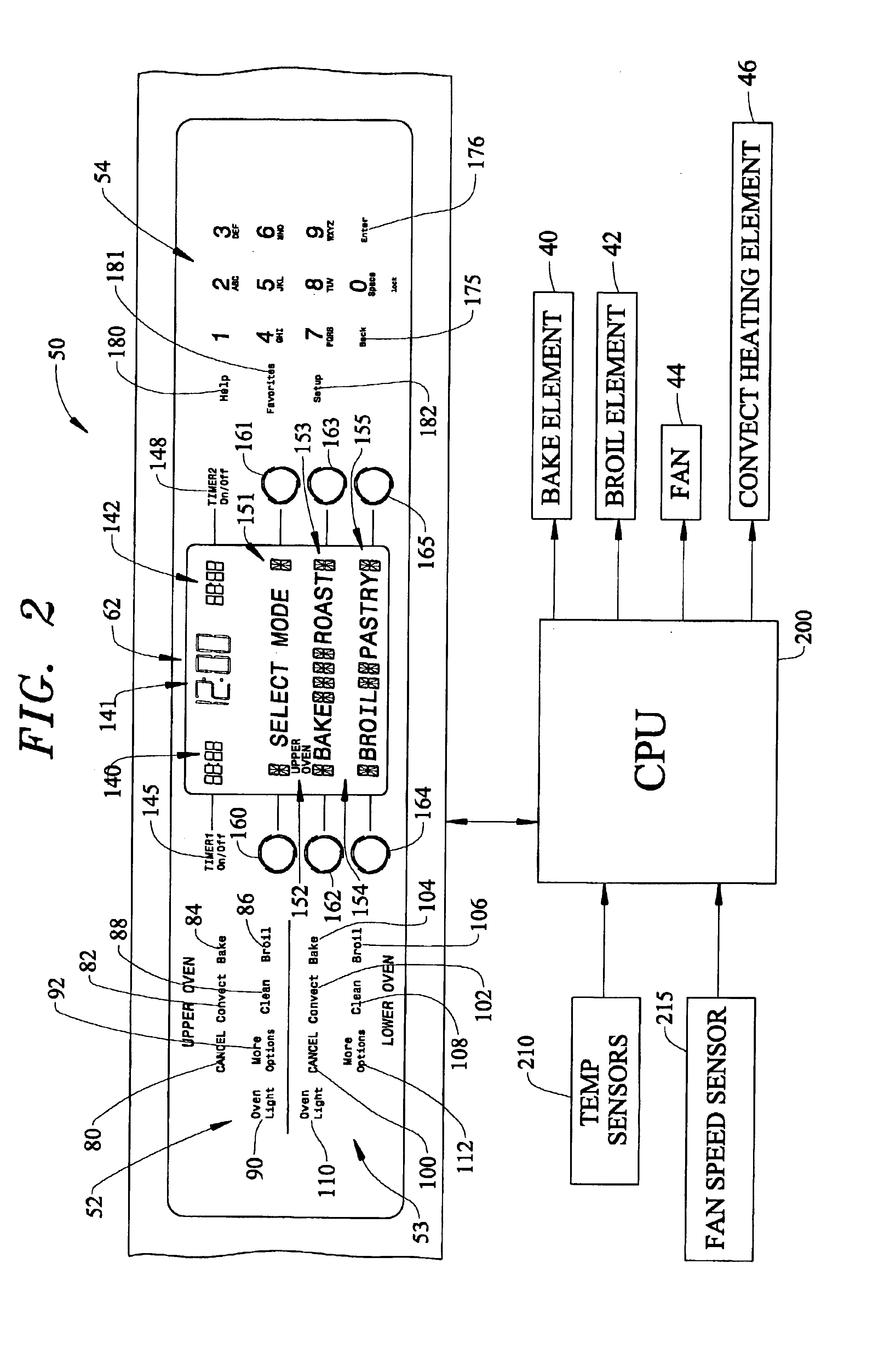
[0007]The present invention is directed to a cooking appliance including a control user interface defined by a control panel arranged with a set of dedicated keys for each of various primary cooking modes. The control panel includes a display having various information display zones and various selection keys which are provided on each side of and aligned with the information display zones. The selection keys are used to input desired options and settings presented in the display.
[0008]In accordance with the most preferred form of the invention, the controller is based on a hierarchical type organization wherein a user selects an initial cooking mode which is visually presented to the user in the display. The controller then navigates the user through a series of sub-menus to establish settings and options associated with each particular cooking mode. For example, if the user presses a convection button, various types of convection modes to choose from are presented in the inform

Problems solved by technology

The luxury of spending time in preparing a meal is becoming less and less affordable.
Of course, when making a wide range of cooking options available to a consumer in a particular cooking appliance, the complexity of operation will certainly increase.

Method used


Image

  • Menu driven control system for a cooking appliance
  • Menu driven control system for a cooking appliance
  • Menu driven control system for a cooking appliance

Examples


Embodiment Construction

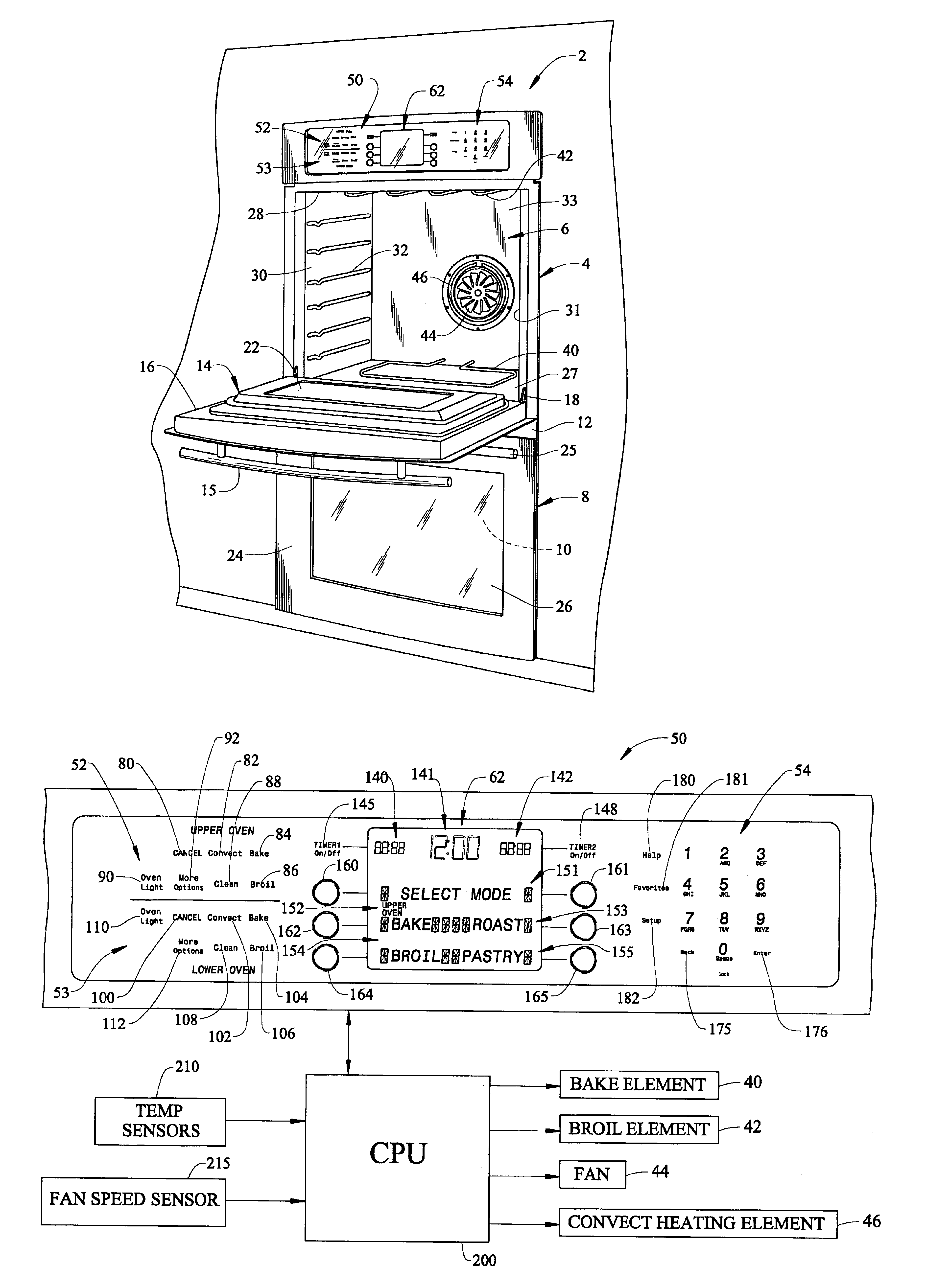
[0014]With initial reference to FIG. 1, a cooking appliance constructed in accordance with the present invention is generally indicated at 2. Cooking appliance 2, as depicted, constitutes a double wall oven. However, it should be understood that the present invention is not limited to this model type and can be incorporated into various types of oven configurations, e.g., cabinet mounted ovens, as well as both slide-in and free standing ranges. In any event, in the embodiment shown, cooking appliance 2 constitutes a dual oven wall unit including an upper oven 4 having upper oven cavity 6 and a lower oven 8 having a lower oven cavity 10. Cooking appliance 2 includes an outer frame 12 for supporting both upper and lower oven cavities 6 and 10.

[0015]In a manner known in the art, a door assembly 14 is provided to selectively provide access to upper oven cavity 6. As shown, door assembly 14 includes a handle 15 at an upper portion 16 thereof. Door assembly 14 is adapted to pivot at a low...


PUM


Abstract

A cooking appliance includes a control user interface defined by a control panel arranged with a set of dedicated keys for each of various primary cooking modes. The control panel includes a display having various information display zones and various buttons which are provided on each side of and aligned with the information display zones. The buttons are used to select options and settings presented in the display. A controller, based on a hierarchical type organization, is employed to select a choice of cooking modes visually presented to a user in the display. The controller then navigates the user through a series of sub-menus to establish settings and options associated with each particular cooking mode.

Description

BACKGROUND OF THE INVENTION[0001]1. Field of the Invention[0002]The present invention pertains to the art of cooking appliances and, more particularly, to a menu driven control system for a cooking appliance.[0003]2. Discussion of the Prior Art[0004]The art of cooking is currently undergoing substantial change. It is no longer the norm to have a family member home all day with time to cook and prepare meals. Today, more and more consumers must rush home from work to prepare meals for themselves or for their families. In today's fast paced society, time is of the essence. The luxury of spending time in preparing a meal is becoming less and less affordable. As such, consumers demand an oven that will cook a meal in less time than conventional ovens, without sacrificing the quality of the prepared food. In order to meet these demands, manufacturers are combining conventional radiant cooking systems with the rapid cook advantages of convection, microwave, and other types of cooking syst...

Claims


Application Information

Patent Timeline
IPC IPC(8): F24C7/08H05B6/80H05B6/68
CPCF24C7/082H05B6/6435H05B6/647H05B6/66
Inventor BECKER, THEODORE A.BOYER, MARK A.FISHER, SUSAN K.JONES, BRIANMEANS, JILL L.
Owner MAYTAG
Why Eureka
Try Eureka