Three dimensional linear machining apparatus

a technology of machining apparatus and machining path, which is applied in the direction of instrumentation, electric programme control, program control, etc., can solve the problems of irregular machining path, inability to uniformly maintain the feed speed of the torch with respect to the workpiece, and inability to achieve uniform feed speed

Inactive Publication Date: 2005-08-16
KAISHA KABUSHIKI
View PDF12 Cites 20 Cited by
  • Summary
  • Abstract
  • Description
  • Claims
  • Application Information

AI Technical Summary

Benefits of technology

[0009]According to this invention, the means for executing machining executes machining on the workpiece by simultaneously controlling the first, second and third axes and the first, second and third rotational axes on the basis of the angular velocity in the first, second and third rotational directions and the moving speed in the first, second and third axial directions which are computed by the means for computing axial speed, so that the workpiece of which sectional shape is irregular shape having a corner can be also successively machined along a machining path passing through the corner, it is not necessary to machine the workpiece every each machining surface as a conventional case, and speedy machining can be actualized. Furthermore, concurrent six-axes cylindrical interpolation instruction is executed so as to correspond the feed speed of the machining portion with respect to the workpiece with the feed speed instructed in the machining program, so that a cut face in a good condition having no surface irregularity can be made with machining while speedy machining is actualized. Besides, the concurrent six-axes cylindrical interpolation instruction is executed by instructing the start point, the intermediate point, the end point and the feed speed in the machining program, so that a CAD / CAM unit and memory capacity for the machining program are not specifically necessary, and the machining can be easily performed without specific skill.
[0011]According to this invention, the means for executing machining executes machining on the workpiece at the speed amended by the means for amending speed on the basis of the judgment of the means for judging ceiling speed, so that successive machining can be correctly executed along the machining path passing through the corner even if the angular velocity of each rotational direction and the moving speed in each axial direction exceed a predetermined ceiling value.
[0013]According to this invention, the means for changing condition for outputting laser beam changes the condition for outputting laser beam when the speed of each axis is amended by the means for amending speed, so that the condition for outputting laser beam according to the amended speed of each axis can be set, and the machining for making a cut face in a good condition having no irregularity can be certainly executed.

Problems solved by technology

In case where the sectional shape of a workpiece to be machined is an irregular shape having a corner, but the feed speed of the torch with respect to the workpiece can not be uniformly maintained in a machining path passing through the corner since the linear / arc interpolation instruction and the cylindrical interpolation instruction can not be simultaneously controlled, so that irregularity may be formed on a surface cut by machining.
That is, it is difficult to maintain a cut surface having no irregurality and to successively machine a member having an irregular shape along the above-mentioned machining path.
For these reasons, the member having the irregular shape is necessary to be machined every each machining face of the workiece, so that much labor and / or long time is required for such operation, and it is difficult to actualize speedy machining.
But, long time is necessary for complex computation in such a machining, and besides, specific skill is also necessary.
Besides, the interpolation instruction of micro line segment is used, so that the machining speed is slow and it is difficult to actualize speedy machining.

Method used


Image

  • Three dimensional linear machining apparatus
  • Three dimensional linear machining apparatus
  • Three dimensional linear machining apparatus

Examples


Embodiment Construction

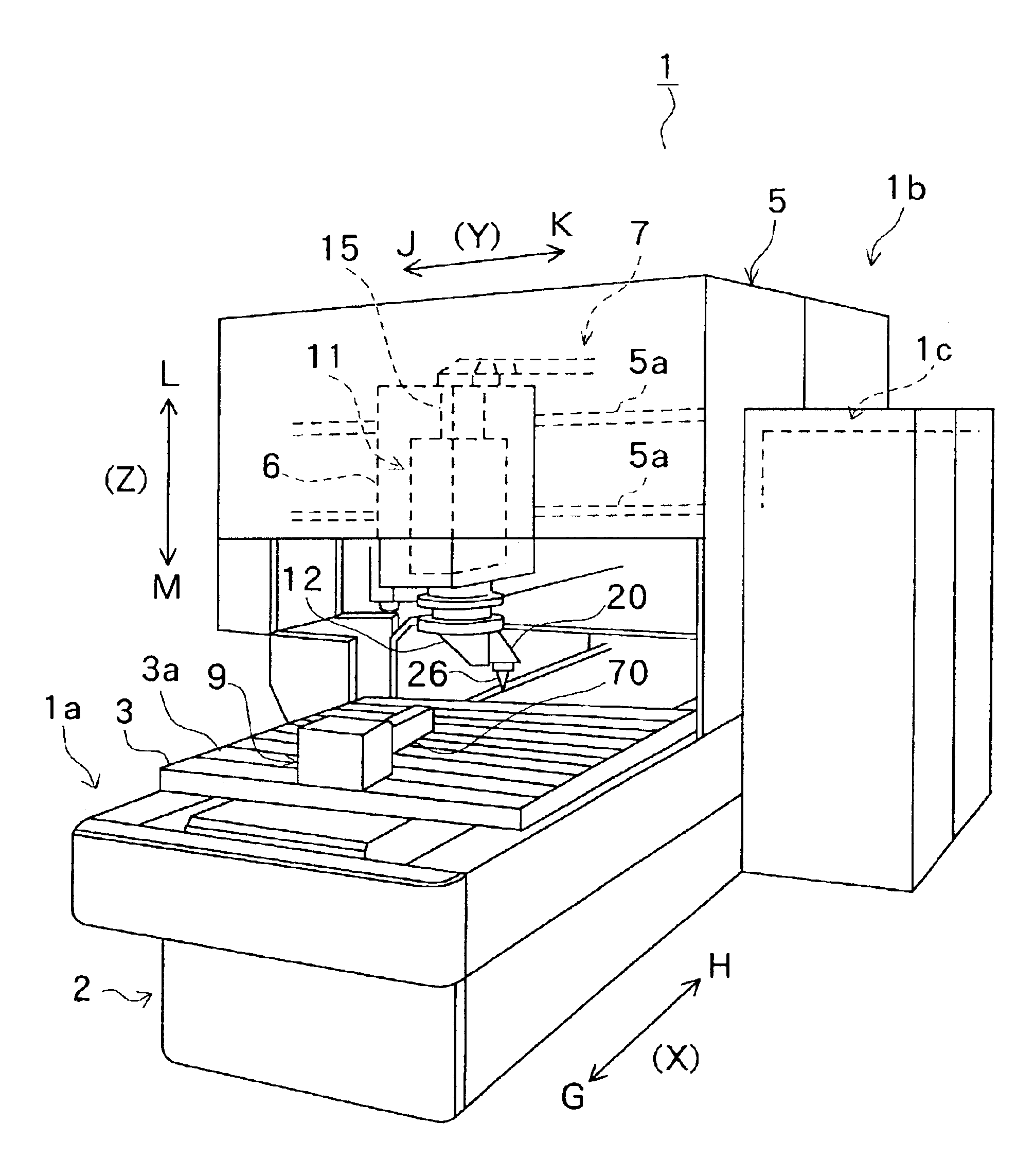
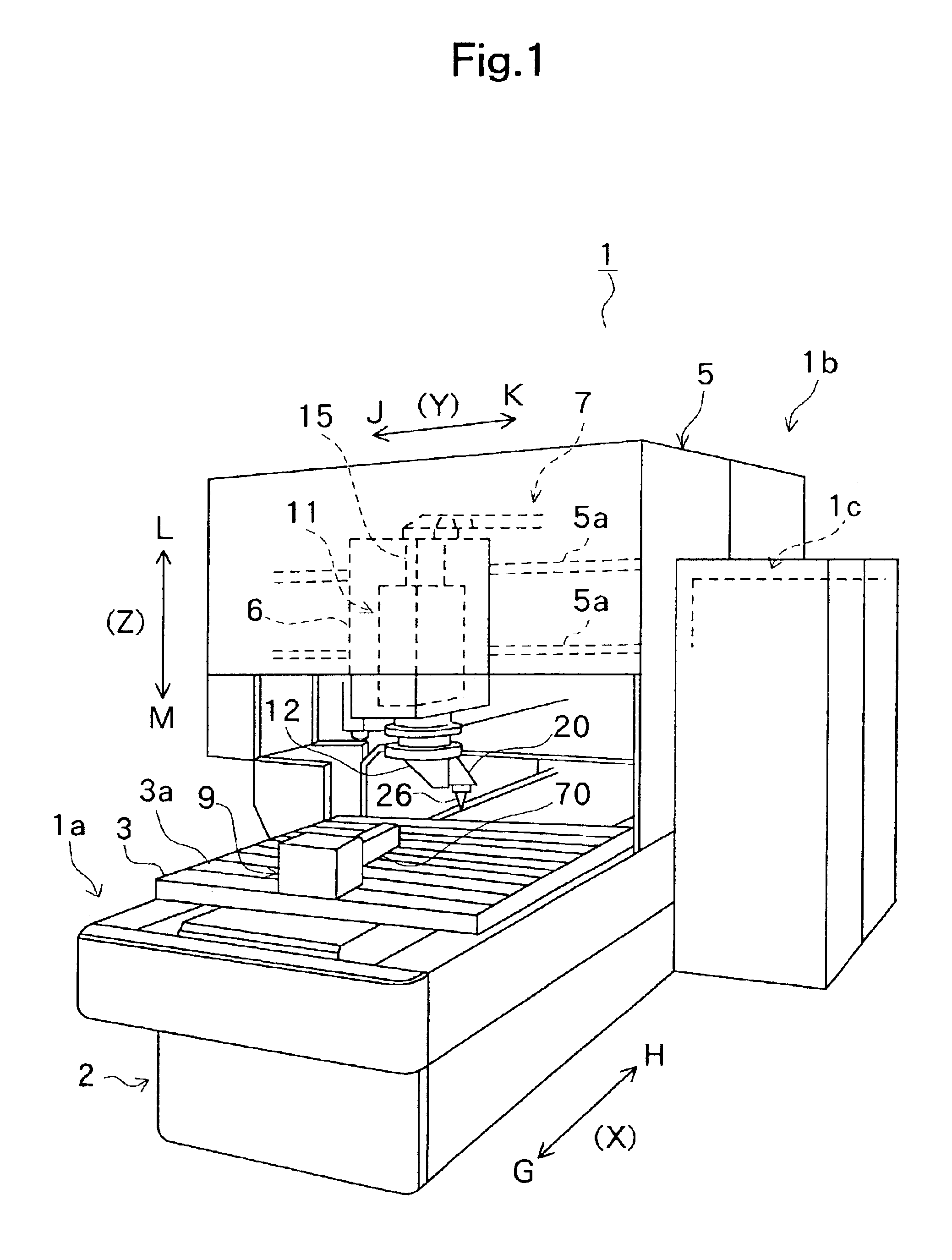
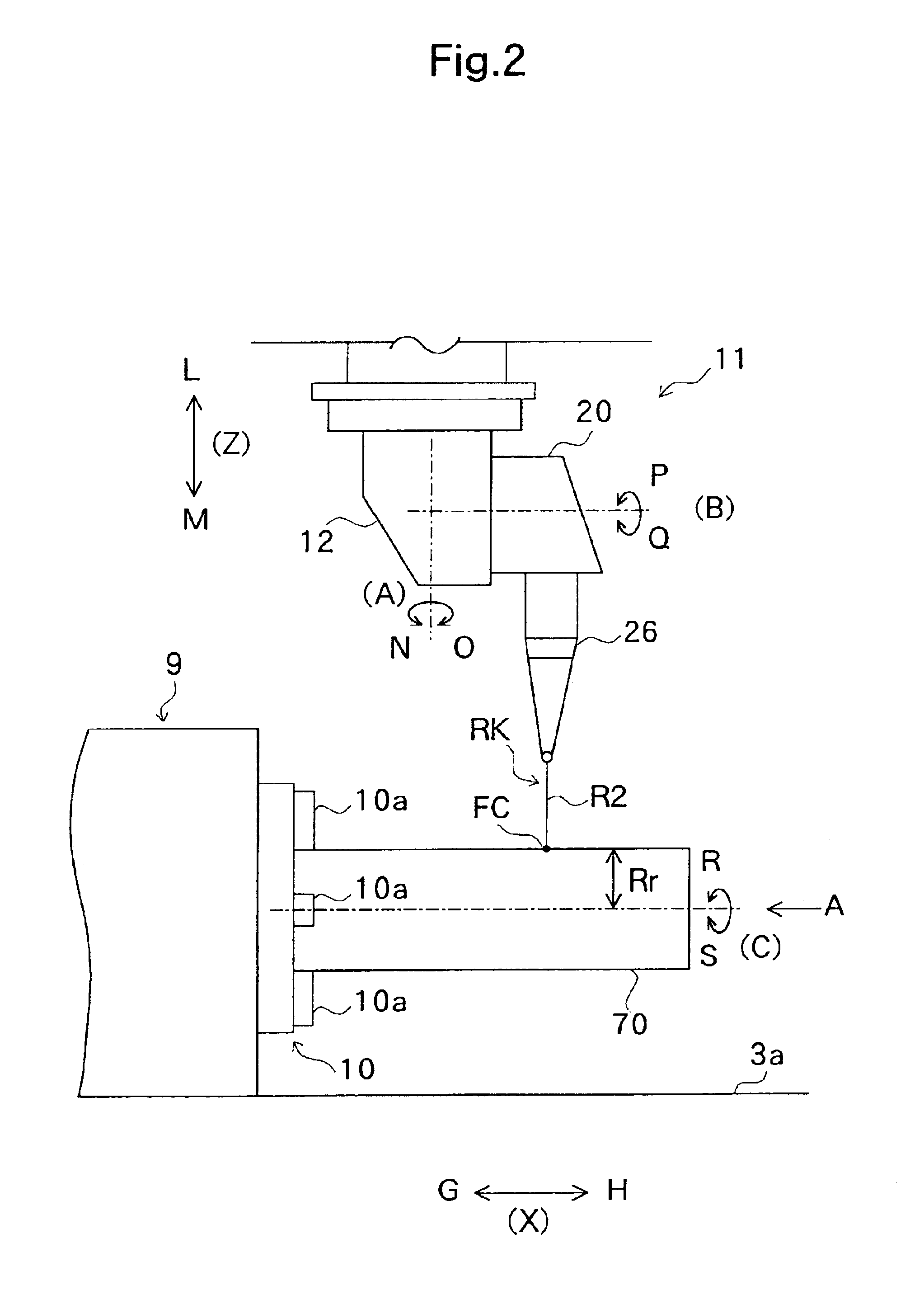
[0024]FIG. 1 is a perspective view for showing an instance of the whole laser beam machine to which the present invention is applied, FIG. 2 is a side view for showing a chuck of the laser beam machine of FIG. 1 and its neighborhood, FIG. 3 is an enlarged sectional view for showing a machining head body of the laser beam machine of FIG. 1, FIG. 4 is a block diagram for showing a control unit of the laser beam machine of FIG. 1, FIG. 5 is a flow chart for showing flow of processing at the time of machining with the laser beam machine, FIG. 6 is a flow chart for showing a program for controlling feed speed, FIG. 7 is a sectional view of a long-shaped member having a section of a rectangle, on which cutting machining is performed according to the present invention, FIG. 8 is a view for showing an imaged scope for inputting code parameter, FIG. 9 is an instance of machining control for a long-shaped member having a section in the shape of a rectangle according to the present invention, ...


PUM

PropertyMeasurementUnit
feed speedaaaaaaaaaa
rotational radiusaaaaaaaaaa
speedaaaaaaaaaa

Abstract

At the time of execution of concurrent six-axes cylindrical interpolation instruction wherein a start point, an intermediate point, an end point and feed speed are instructed in a machining program PRO, a machining data computing portion 59 computes angular velocity of first, second, and third rotational axis directions and moving speed of first, second and third axial directions so as to correspond the feed speed of a torch with respect to a workpiece with the feed speed instructed in the machining program PRO, and the machining control portion 55 simultaneously controls the first, second and third axes and the first, second and third rotational axes on the basis of the angular velocity and the moving speed which are computed so as to rotate a chuck holding the workpiece and to move the torch, so that machining on the workpiece is executed.

Description

BACKGROUND OF THE INVENTION[0001]The present invention relates to a three dimensional linear machining apparatus for three dimensional machining on a long-shaped member, such as a pipe, such as a laser beam machine, a plasma cutting machine, and a gas cutting machine.[0002]Such kind of conventional three dimensional linear machine which has been proposed is the three dimensional laser beam machine wherein the direction of a torch from which laser beam is radiated is three-dimensionally adjustable with respect to a workpiece. Such a three-dimensional laser beam machine can three-dimensionally machine a workpiece by a linear / arc interpolation instruction for moving and driving a torch on a straight line / an arc or a cylindrical interpolation instruction for rotating a workpiece. In case where the sectional shape of a workpiece to be machined is an irregular shape having a corner, but the feed speed of the torch with respect to the workpiece can not be uniformly maintained in a machinin...

Claims


Application Information

Patent Timeline
Patent Type & Authority Patents(United States)
IPC IPC(8): B23K26/08G05B19/4103B23K26/00G05B19/416
CPCB23K26/08B23K26/0884G05B2219/39578G05B2219/45041
Inventor YAMAZAKI, TSUNEHIKOMIYAGAWA, NAOOMIINOUE, TOSHIHIKO
Owner KAISHA KABUSHIKI
Why Eureka
Try Eureka