Electrophoresis separator

Inactive Publication Date: 2005-08-16
WEALTEC ENTERPRISE
View PDF1 Cites 12 Cited by
  • Summary
  • Abstract
  • Description
  • Claims
  • Application Information

AI Technical Summary

Benefits of technology

[0008]Another object of the electrophoresis separator of the present invention is to connect two clamping sheets to form a structure of which positioning is sure for receiving a carrier which receives sample solution therein. In which, positioning pins and positioning holes are provided on the two clamping sheets respectively. There are protruding sockets all of a specific height provided on one of the two clamping sheets on the surface to be contacted with the other clamping sheet. When the two clamping sheets are abutted upon each other, the protruding sockets can form a crevice between the two. This will enable an operator to position the clamping sheets of the carrier promptly and get a thickness of the gel accurately after shaping.
[0010]A further object of the electrophoresis separator of the present invention is to provide elastic sheets sandwiched between the two clamping sheets of each carrier in order to increase compactness between the two clamping sheets and help shaping of the gel so as to avoid gel spilling.

Problems solved by technology

The breakage phenomenon of the glass sheets (A1) happens easily during the dismantling procedure and makes them unable to use again.
Thereby, the whole production procedure of the sample becomes complicated and is subjected to causing damage of the device and the sample.
However, there are more than four points to be fixed for every set of glass sheets (A1), it is impossible to adjust the depth of every screw (A51) in a fast and accurate way.
Thus the crevice between the glass sheets (A1) will be uneven, and especially the glass sheets (A1) will be damaged because of over rotating of the screw (A51).
Then the carrier is positioned through a complicated fixing action, so it is still not as convenient in use as expected.

Method used


Image

  • Electrophoresis separator
  • Electrophoresis separator
  • Electrophoresis separator

Examples


Embodiment Construction

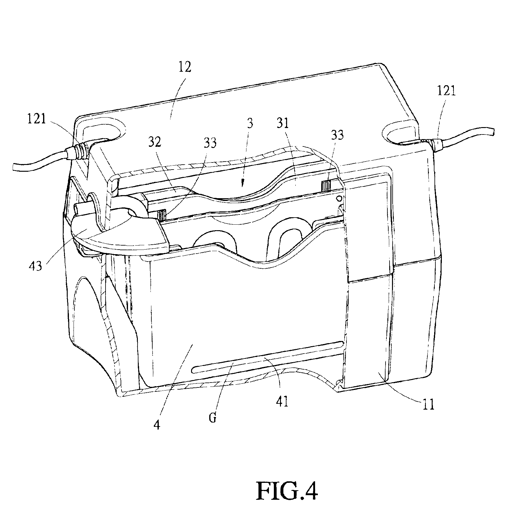
[0027]The electrophoresis separator of the present invention is shown in FIG. 4 and FIG. 5, the structure of the whole device is comprised of an electrophoresis tank 11 and a receiving tank 4 as the main body. The electrodes for driving the electric current are provided in the electrophoresis tank 11 and the receiving tank 4 separately. A cathode 21 and an anode 22 are provided simultaneously on the top of the receiving tank 4 in the structure of the embodiment shown. And the electrophoresis tank 11 and the receiving tank 4 are filled with electric conducting liquid 24 to form an electric current passage. Besides, the anode 21 and the cathode 22 are connected to the electric conducting liquid 24 in the electrophoresis tank 11 and the receiving tank 4 via conductors 23. Carriers 3 each for receiving a sample are immersed in the electric conducting liquid 24 of the receiving tank 4, and an upper lid 12 is used to cover the entire reaction device. An electrode connector 121 is provided...


PUM

PropertyMeasurementUnit
Thicknessaaaaaaaaaa
Currentaaaaaaaaaa

Abstract

An electrophoresis separator of which a receiving tank used for placing therein carriers has slots on the two sides thereof, one side of each carrier has a notch matching with a corresponding slot; so that when the carrier is inserted in the receiving tank, a blocking piece provided at the bottom of the receiving tank covers the bottom of the carrier and the crevice between the notch and the receiving tank; and a blocking sheet is inserted into the slot and notch. The blocking sheet can be removed from the slot and notch after the gel in the carrier is fixed and shaped, then the gel can contact the electric conducting liquid in the electrophoresis tank through the slot and notch; the other end of the gel body will contact the electric conducting liquid through an upper opening of the carrier directly. When electrodes are activated, electric current floating is resulted to cause an effect of molecule separation and analysis for the sample in the gel.

Description

BACKGROUND OF THE INVENTION[0001]1. Field of the Invention[0002]The invention is related to an electrophoresis separator, and especially to such an electrophoresis separator by which production of a sample is more convenient and the sample can be connected to the whole device more easily, thereby the whole electrophoresis separating engineering can be carried out more smoothly and surely.[0003]2. Description of the Prior Art[0004]An electrophoresis method in biologic technology mainly aims at separating and analysis of DNA, RNA and protein. Macromolecules of DNA, RNA and protein are separated according to the ratio of electric charge to mass, and the molecules are driven by means of electric current to make the molecules float on the gel of the substance. While in moving, the molecules will be separated because of the differences of the electric charges carried by the ion-natured ingredient and of the sizes of these molecules themselves. The sample solution to be separated and analy...

Claims


Application Information

Patent Timeline
IPC IPC(8): B01D57/02G01N27/447
CPCB01D57/02G01N27/44756
Inventor CHEN, HUI-WAN
Owner WEALTEC ENTERPRISE
Why Eureka
Try Eureka