
Humidifier with disinfection unit

Active Publication Date: 2021-06-24
KONINKLJIJKE PHILIPS NV
View PDF0 Cites 2 Cited by
  • Summary
  • Abstract
  • Description
  • Claims
  • Application Information

AI Technical Summary

Benefits of technology

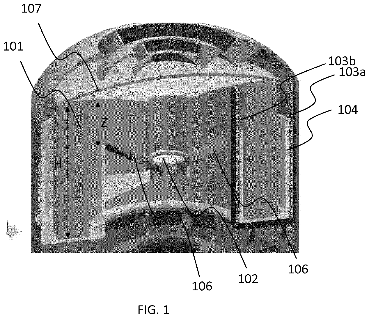
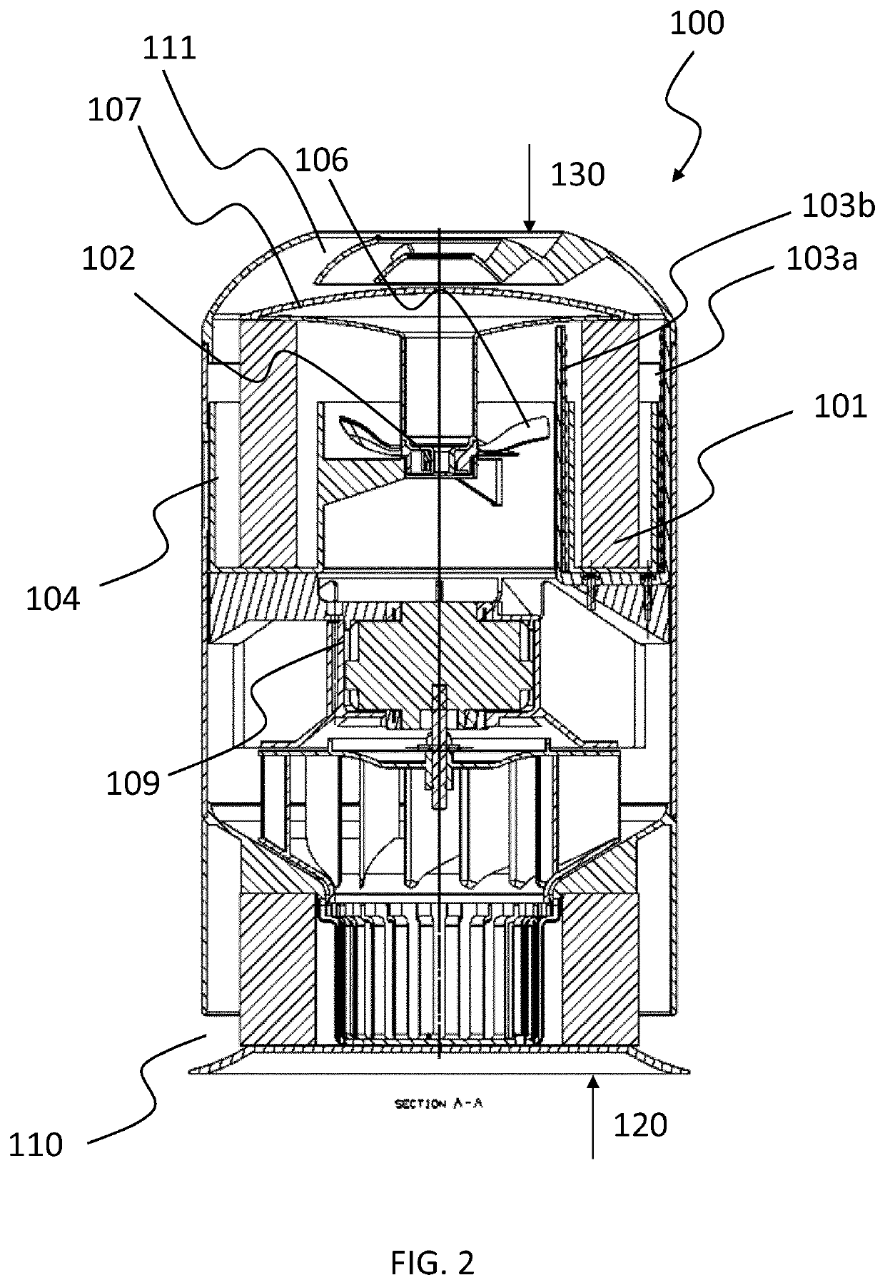
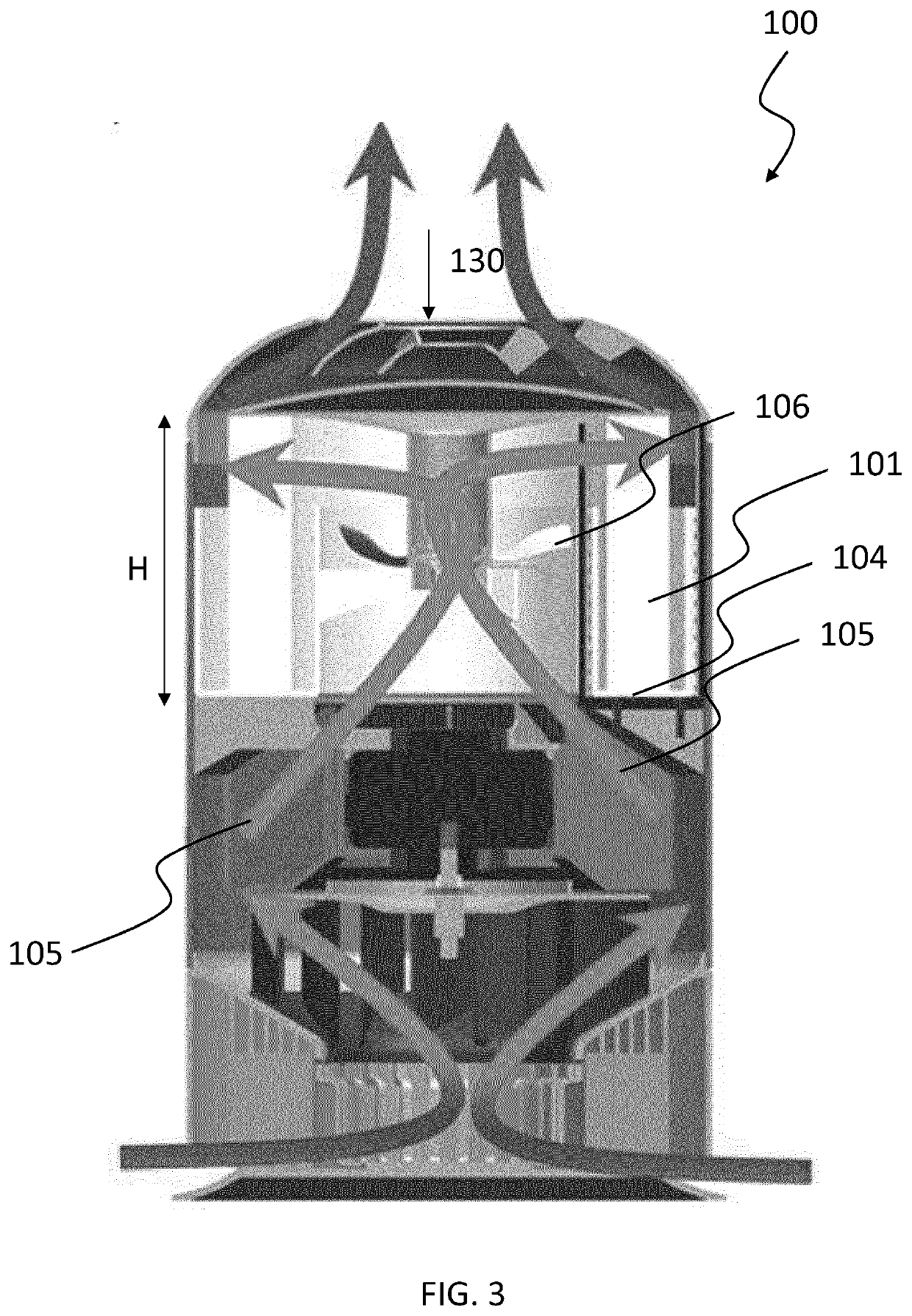
This patent describes a humidifier that uses a hollow-cylindrically shaped water tank where a disinfection unit is located to disinfect the water tank and its content. The invention also includes a means for motorlessly rotating the wick using an air flow, which reduces manufacturing and total costs. The wick is designed to partially float in water, making it easier to rotate. These technical effects increase the compactness, reduce costs, and improve the disinfection effectiveness of the humidifier.

Problems solved by technology

This increases the disinfection effectivity of the system.

Method used


Image

  • Humidifier with disinfection unit
  • Humidifier with disinfection unit
  • Humidifier with disinfection unit

Examples


Embodiment Construction

[0032]The present invention will be described with respect to particular embodiments and with reference to certain drawings but the invention is not limited thereto but only by the claims. The drawings described are only schematic and are non-limiting. In the drawings, the size of some of the elements may be exaggerated and not drawn on scale for illustrative purposes. The dimensions and the relative dimensions do not correspond to actual reductions to practice of the invention.

[0033]Furthermore, the terms first, second and the like in the description and in the claims, are used for distinguishing between similar elements and not necessarily for describing a sequence, either temporally, spatially, in ranking or in any other manner. It is to be understood that the terms so used are interchangeable under appropriate circumstances and that the embodiments of the invention described herein are capable of operation in other sequences than described or illustrated herein.

[0034]It is to be...


PUM

PropertyMeasurementUnit
Nanoscale particle sizeaaaaaaaaaa
Forceaaaaaaaaaa
Flow rateaaaaaaaaaa

Abstract

Presented is a humidifier, comprising: a rotatable wick (101); a means for rotating the wick (102); characterized in that: the humidifier further comprises a disinfection unit (103a, 103b) adapted such that different parts of the wick are disinfected when the wick rotates.

Description

FIELD OF THE INVENTION[0001]The present invention relates to humidifiers. In particular, the invention relates to humidifiers with disinfection capabilities.BACKGROUND OF THE INVENTION[0002]Humidifiers are available from many brands and are widely used to increase the humidity level of air in indoor spaces. Different architectures have been developed based on different principles. These humidifiers share a common feature, namely, a water tank which is a reservoir for the water used for humidifying the air.[0003]A problem related to water being present in the water tank is the growth of microorganisms. This is disturbing to the user as over time it creates an unpleasant smell. Further, this may also lead to health issues for the user, for example when microorganisms and / or their by-products such as Microbial Volatile Organic Compounds (MVOCs) are released into the air. The growth of microorganisms also occurs inside the wick which absorbs water from the water tank and which is used t...

Claims


Application Information

Patent Timeline
IPC IPC(8): A61L9/20F24F8/22F24F6/16
CPCA61L9/20F24F8/22F24F2006/008A61L2202/11F24F6/16A61L2/085A61L2/10F24F6/06F24F8/20F24F3/14B01F23/20
Inventor WANG, BAOSCHEJA, MICHAEL MARTINMCGARVA, JOHN ROBERT
Owner KONINKLJIJKE PHILIPS NV
Learn More