
Photobooth with improved accessibility and optical characteristics

a technology of optical characteristics and access points, applied in the field of photographic equipment, can solve the problem that the conventional photographic equipment b>100/b> cannot be said to be suitable for such patients

Inactive Publication Date: 2005-08-09
SONY CORP
View PDF12 Cites 16 Cited by
  • Summary
  • Abstract
  • Description
  • Claims
  • Application Information

AI Technical Summary

Benefits of technology

The present invention provides a booth-type photographic apparatus that allows even handicapped individuals on a wheelchair or using other aids to easily take an identification picture of themselves. The apparatus is easy to operate by attendants or other individuals and can be installed stably on a floor surface. It includes a housing with a photo compartment, a photographic means for capturing the object image, a printing means for printing the object image onto photographic paper, and a shading member for protecting the photographic means. The apparatus also has an operating means for controlling its operation. These technical effects make the apparatus more convenient and user-friendly for photographic purposes.

Problems solved by technology

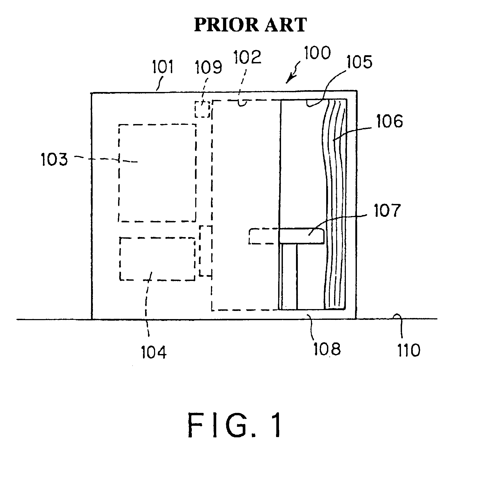
The aforementioned conventional photographic apparatus 100 cannot be said to be suitable for such patients.

Method used


Image

  • Photobooth with improved accessibility and optical characteristics
  • Photobooth with improved accessibility and optical characteristics
  • Photobooth with improved accessibility and optical characteristics

Examples


Embodiment Construction

[0030]The photographic apparatus according to the present invention will be described in detail below with reference to the accompanying drawings.

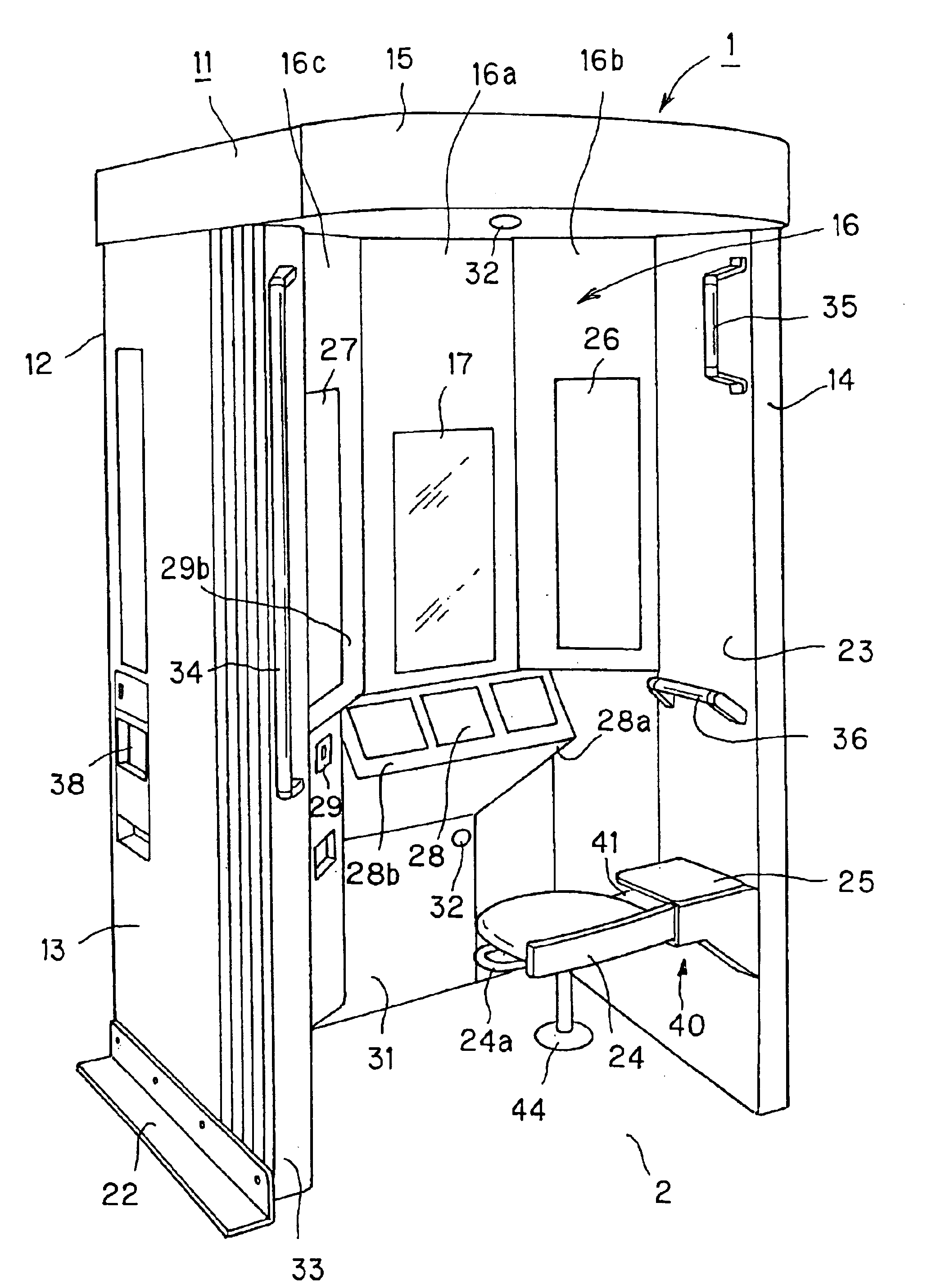
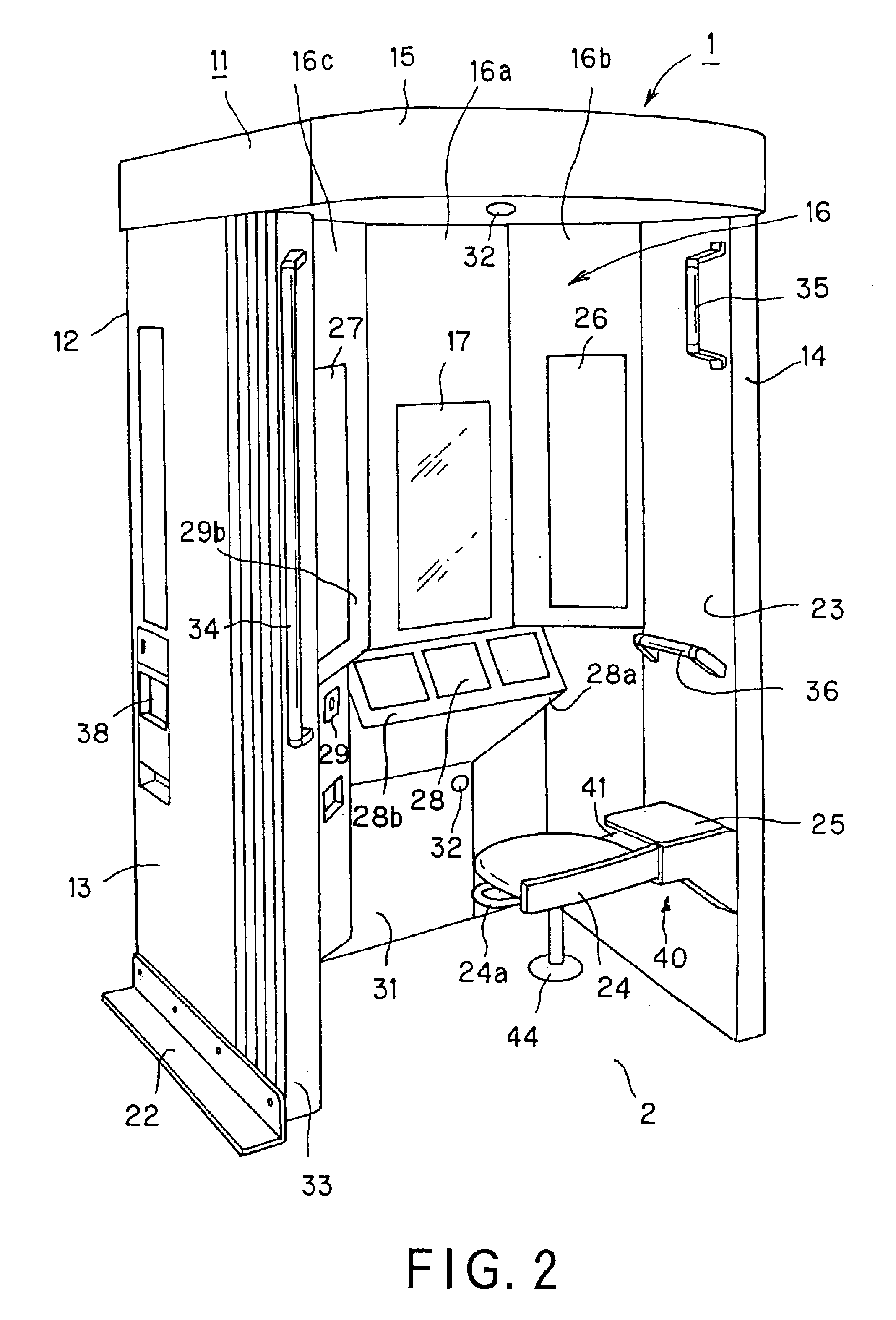
[0031]Referring now to FIGS. 2 to 4, there is schematically illustrated an embodiment of the photographic apparatus according to the present invention, generally indicated with a reference number 1. This photographic apparatus 1 is of a booth type to be installed in a hospital or the like for making a facial portrait of a patient or the like. As shown, the photographic apparatus 1 (will be referred to as “photo booth” hereinafter) includes a housing 11 as a main body. The housing 11 consists of a rear panel 12, side panels 13 and 14 provided oppositely to each other and at opposite lateral ends of the rear panel 12, and a top panel 15 provided between the side panels 13 and 14 and at the tops of the latter panels to cover the opening between the side panels 13 and 14 and form a ceiling of the housing 11. Thus, the rear panel 12, pair of si...


PUM


Abstract

In a photographic apparatus (1), there are included a housing (11) consisting of a pair of side panels (13, 14) and a top panel (15) provided contiguously to the side panels (13, 14) in pair, these panels defining together a photo compartment (16) in the housing (11), a photographic unit (17) provided at the rear side of the housing (11) to take a picture of an object person inside the photo compartment (16), printers (18, 19) installed to the housing (11) to print an image of the object person, captured by the photographic unit (17), onto a photographic paper and eject the photographic paper having the object image printed thereon to a photo outlet (38), and a curtain (33) provided, by hanging, on the top panel (15) at the front side, opposite to the rear side, of the housing (11) to face the photographic unit (17). One (13) of the side panels (13, 14) is formed narrower than the other (14). The housing (11) is generally flush, at the bottom thereof, with the floor surface. The area extending from the front end of the housing (11) to that of the narrower side panel (13) is an entrance (23) for the object person entering the photo chamber (16). Because of this wide entrance (23), even a person sitting on a wheelchair or using any other aid can easily enter the photo compartment (16) for photography.

Description

TECHNICAL FIELD[0001]The present invention relates to a photographic apparatus for an identification picture etc.[0002]This application claims the priority of the Japanese Patent Application No. 2002-103039 filed on Apr. 4, 2002, the entirety of which is incorporated by reference herein.BACKGROUND ART[0003]FIG. 1 schematically illustrates a conventional photographic, generally indicated with a reference number 100, for an identification picture. As shown, the photographic apparatus 100 consists of a generally rectangular housing 101 having a photo compartment 102 defined therein. The housing 101 has built therein a photographic unit 103 to take a picture of a person as an object (will be referred to as “object person” hereinafter) having entered the photo compartment 102, and a printer 104 to print out a picture taken by the photographic unit 103.[0004]Also, the housing 101 has an entrance 105 for access to inside the photo compartment 102. The entrance 105 is provided with a shade ...

Claims


Application Information

Patent Timeline
Patent Type & Authority Patents(United States)
IPC IPC(8): G03B17/48G03B17/53G07F17/26
CPCG03B17/53G07F17/26
Inventor NAKANISHI, TOSHIAKIUEHARA, MASAHIROTAKANO, HIROAKI
Owner SONY CORP
Learn More