Ink-jet head and ink-jet printer

a technology of inkjet printer and inkjet head, which is applied in the direction of printing, etc., can solve the problems of passage unit deviating from the designed position, unable to help being decreased, and the distance from the nozzle open face to the bottom face of the common ink chamber, etc., to achieve good ejection performance and suppress the deformation of the passage unit

Inactive Publication Date: 2005-08-09
BROTHER KOGYO KK
View PDF20 Cites 26 Cited by
  • Summary
  • Abstract
  • Description
  • Claims
  • Application Information

AI Technical Summary

Benefits of technology

[0009]An object of the present invention is to provide a small-sized ink-jet head capable of suppressing the deformation of a passage unit due to a capping force with ensuring a cross-sectional area of a common ink chamber necessary for obtaining a good ejection performance.
[0010]Another object of the present invention is to provide an ink-jet printer capable of suppressing the deformation of a passage unit due to a capping force and reducing the size of an ink-jet head with ensuring a cross-sectional area of a common ink chamber necessary for obtaining a good ejection performance.
[0012]According to the invention, the reinforcement portion is provided on the wall of the common ink chamber opposite to the second flat face of the passage unit. This improves the strength of the passage unit against capping force applied to the passage unit by a lip when the lip is brought into contact with a nozzle open face of the passage unit. Therefore, reduction in size of the passage unit can be realized with ensuring a cross-sectional area of the common ink chamber necessary for obtaining good ejection performance.
[0013]That is, not simply the thickness of the wall of the common ink chamber opposite to the second flat face of the passage unit is increased but part of the wall is left thin and the thickness of only the remaining part of the wall is increased by the reinforcement portion. Thereby, an increase in strength and ensuring a necessary cross-sectional area are compatible. Thus, an ink-jet head can be obtained that is less deformable even when capping force is applied and superior in ejection performance.
[0016]According to the invention, the pressure applied to the passage unit by a lip when the lip is brought into contact with a nozzle open face of the passage unit can be lowered. Therefore, even when an ink-jet head in which such a stepped portion as described above is not provided is used, the ink-jet head can be reduced in size with suppressing deformation of the passage unit due to capping force.

Problems solved by technology

Therefore, if reduction in size of the passage unit and a highly dense arrangement of nozzles are intended to be realized with suppressing a decrease in the cross section of the common ink chamber, the distance from the nozzle open face to the bottom face of the common ink chamber, that is, the thickness of the bottom wall of the common ink chamber, cannot help being decreased.
The position of the lip to be in contact with the passage unit may deviate from the designed position because of a positional error in assembling the printer.
However, if the distance between the inner edge of the lip and the periphery of the nozzles is too large, the outer edge of the lip is close to the bottom wall of the common ink chamber.

Method used


Image

  • Ink-jet head and ink-jet printer
  • Ink-jet head and ink-jet printer
  • Ink-jet head and ink-jet printer

Examples


first embodiment

[0043]FIG. 1 is a perspective view illustrating a general construction of a color ink-jet printer including ink-jet heads according to the present invention. As illustrated in FIG. 1, in a head assembly 63 of the color ink-jet printer 1, four piezoelectric ink-jet heads 6 are fixed to a main frame 68 for ejecting four color inks (for example, cyan, magenta, yellow, and black), respectively. Further, four ink cartridges 61 filled with the respective color inks are attached to the main frame 68 so as to be detachable. The main frame 68 is fixed to a carriage 64, which is driven by a drive system 65 to be reciprocated along a straight line. A platen roller 66 for transporting a paper is disposed such that the central axis of the platen roller 66 extends along the reciprocation of the carriage 64. The platen roller 66 is opposed to the ink-jet heads 6.

[0044]The carriage 64 is supported by a guide shaft 71 and a guide plate 72, which are disposed parallel to the axis of the platen roller...

third embodiment

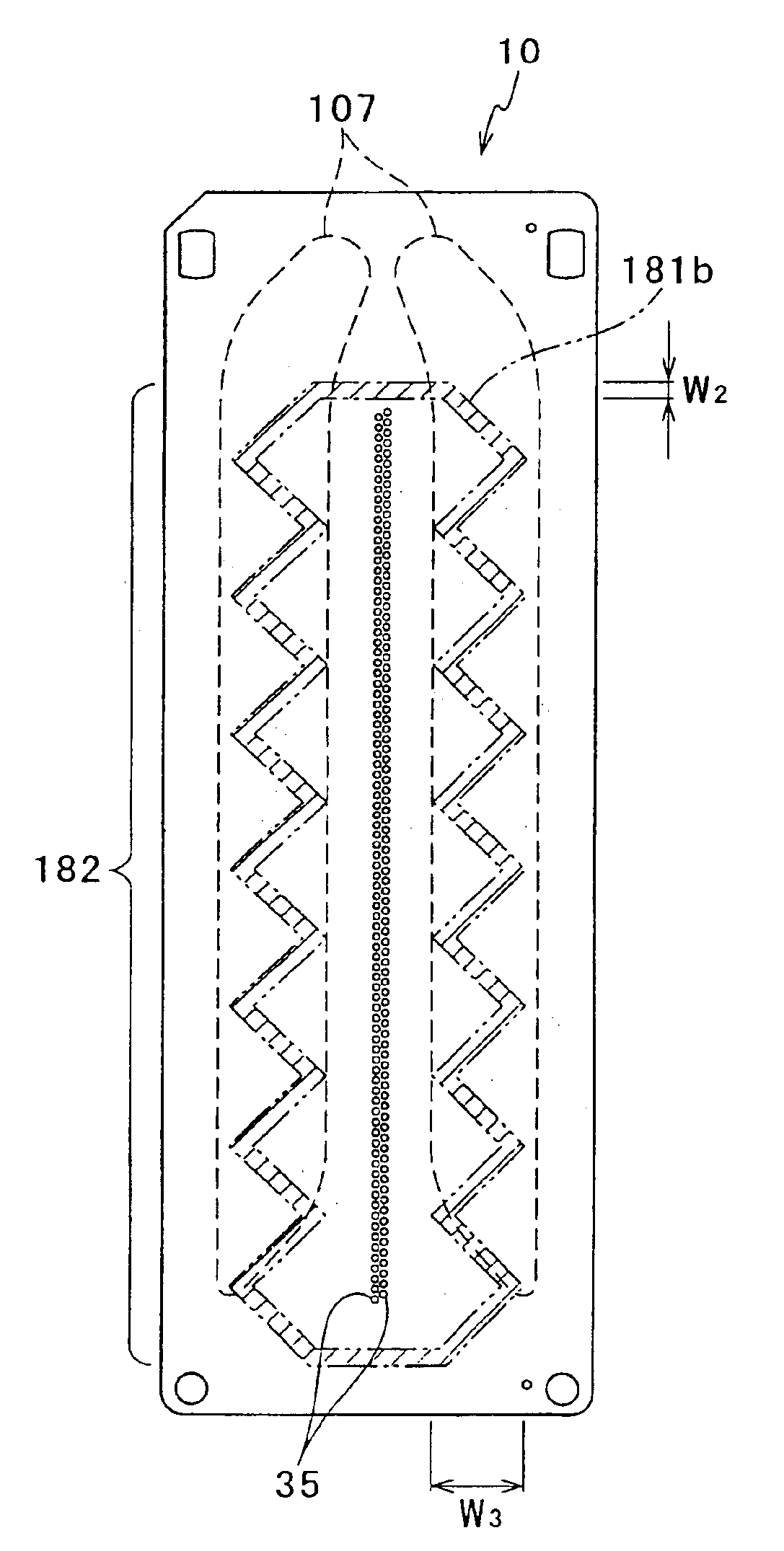
[0106]The shape of the tip end of the lip to be in contact with the portion of the nozzle plate below each common ink chamber is not limited to such a zigzag shape or a thick shape as in the above-described second or For example, the lip may have a contact face in a shape extending radially from a portion for protecting nozzles. That is, the tip end of the lip may have a shape such that the portion of the lip corresponding to each common ink chamber 107 has a large contact area to the nozzle open face and the capping force propagated to the bottom wall of each common ink chamber 107 can be dispersed.

[0107]In the above-described embodiments, each pressure generation portion in the actuator unit utilizes the piezoelectric effect. However, the present invention is not limited to this. For example, electrostatic pressure generation portions maybe used. Further, each plate 11 to 14 is not limited to metal. For example, they may be made of a resin or is the like.


PUM


Abstract

An ink-jet head comprises pressure chambers arranged along a first flat face, and nozzles each open in a second flat face opposing to the first flat face. The nozzles are connected to the respective pressure chambers. The ink-jet head further comprises a common ink chamber extending along an arrangement of the nozzles. The common ink chamber is connected to each pressure chamber to supply ink to the pressure chamber. The ink-jet head further comprises a wall provided between the second flat face and a wall surface of the common ink chamber. The wall comprises a bottom at a distance not less than a predetermined distance from the second flat face, and a reinforcement portion at a distance more than the predetermined distance from the second flat face.

Description

BACKGROUND OF THE INVENTION[0001]1. Field of the Invention[0002]The present invention relates to an ink-jet head for forming an image on a print surface by ejecting droplets of ink. The present invention also relates to an ink-jet printer including an ink-jet head.[0003]2. Description of the Related Art[0004]An ink-jet head and an ink-jet printer including the ink-jet head are known in which pressure chambers are arranged along one flat face of a flat passage unit, and each pressure chamber is connected to a nozzle open in the other flat face of the flat passage unit, nozzle open face, and to a common ink chamber, manifold passage, disposed within the passage unit (see U.S. Patent Application No. 2001 / 0020968). In such an ink-jet head, in general, an actuator unit is bonded to the passage unit to cover the open face of each pressure chamber. The actuator unit includes a piezoelectric element. By the piezoelectric effect obtained by the piezoelectric element, the volume of each press...

Claims


Application Information

Patent Timeline
Patent Type & Authority Patents(United States)
IPC IPC(8): B41J2/14
CPCB41J2/14209B41J2002/14217B41J2002/14225B41J2002/14306B41J2002/14419
Inventor ITO, ATSUSHITAKAHASHI, YOSHIKAZU
Owner BROTHER KOGYO KK
Why Eureka
Try Eureka