Support structure with Y-shaped support stand

Active Publication Date: 2005-08-09
VERTEX AEROSPACE LLC
View PDF7 Cites 7 Cited by
  • Summary
  • Abstract
  • Description
  • Claims
  • Application Information

AI Technical Summary

Benefits of technology

[0007]The present invention provides a support structure including a support stand that is used to support an object during maintenance, manufacturing, and the like. The object to be worked on is supported reliability and safely. The support stand allows excellent access to the supported object and provides some on-board capability. The support stand is fully adjustable both horizontally and vertically to improve access and versatility. It is movable and highly maneuverable, facilitating its use in congested areas and in moving from one area to another. Its design is modular and allows the support structure to be readily disassembled for transport from location to location, and to be temporarily stored at one location while not in service in a space-efficient manner.
[0012]The Y-shape of the support stand provides excellent rolling maneuverability in a tricycle-like manner so that the support stand may be wheeled into tight spaces and also through congested areas. For example, the Y-shape allows the support stand and its supported article to be wheeled through narrow doorways by a progressive movement in which one end of the support stand, usually the narrow end having the leading columns, is angled and moved through the doorway, the support stand is straightened, and the other end of the support stand is angled and moved through the doorway. The Y-shape and the adjustability also facilitate access to the supported article and the use of the single support stand on a variety of types of supported articles. The Y-shape allows a number of the support stands to be compactly stored in a nested manner, so that they occupy minimal space when not in use. The adjustability feature of the support stand also allows it to be disassembled for transport and then readily re-assembled as needed.

Problems solved by technology

Many types of military and civilian apparatus have become so complex that at least some portions of their maintenance must be performed at specialized maintenance locations away from the normal operating locations.

Method used


Image

  • Support structure with Y-shaped support stand
  • Support structure with Y-shaped support stand
  • Support structure with Y-shaped support stand

Examples


Embodiment Construction

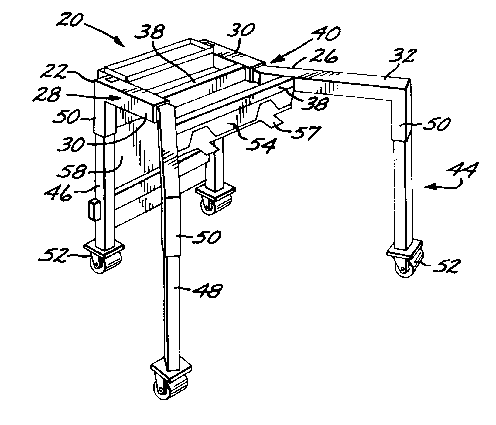
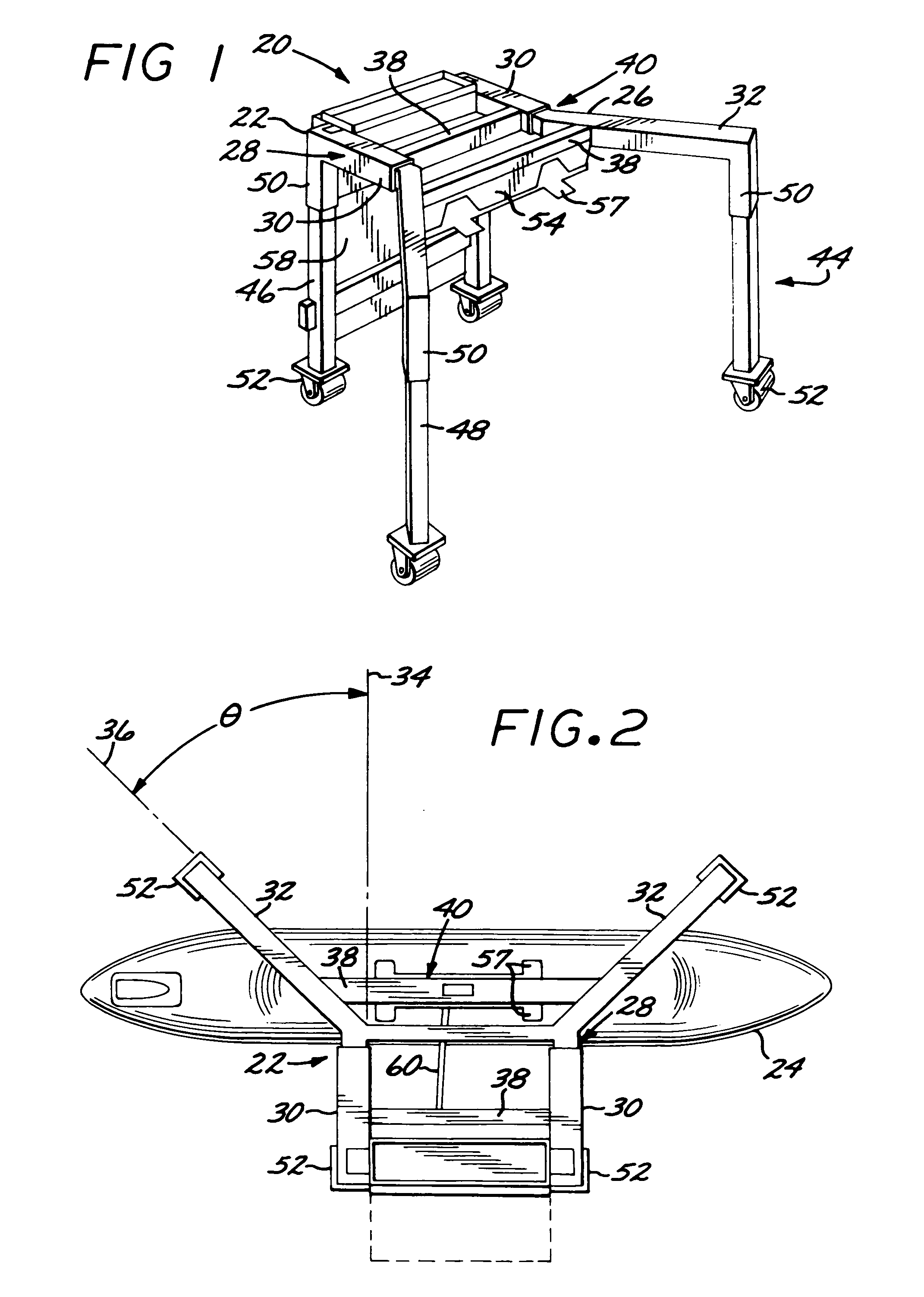
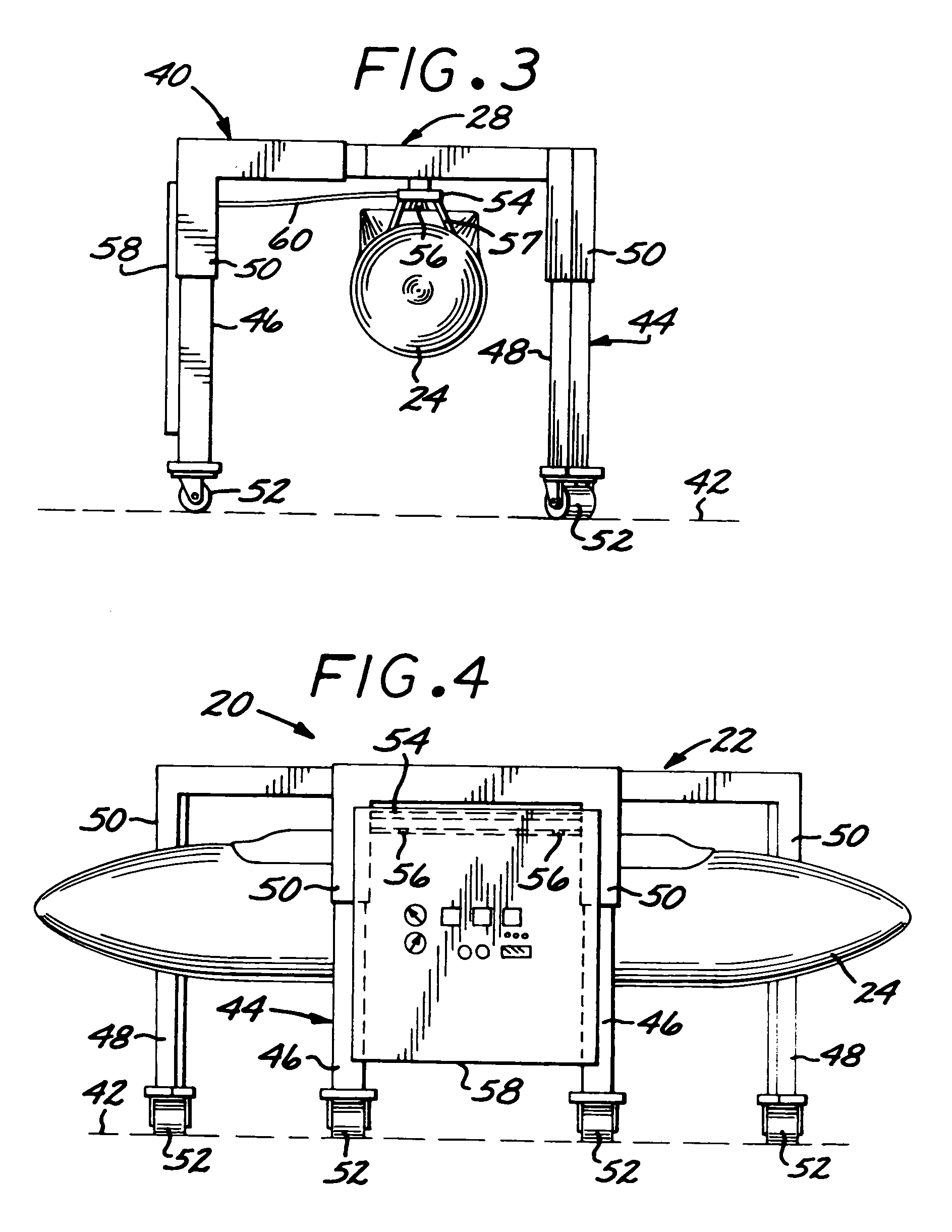
[0018]A preferred embodiment of a support structure 20 is illustrated in FIGS. 1–4. The support structure includes a support stand 22, seen in all of FIGS. 1–4. Optionally, a supported article 24 may be present, as seen in FIGS. 2–4. In a preferred embodiment, the supported article 24 is an aircraft store such as a reconnaissance pod, as illustrated in FIGS. 2–4. A reconnaissance pod of particular interest is the Shared Reconnaissance Pod (SHARP). The support stand 22, either as illustrated or with slight variations to accommodate different shapes, may be used with a wide variety of other types of supported payload articles 24 for both military and civilian applications.

[0019]The support stand 22 includes a pair of side pieces 26. Each side piece 26 comprises a main beam 28. A length of the main beam 28 is desirably, but not necessarily, adjustable with a sliding adjustment 30. In a preferred approach, the sliding adjustment is in the form of a tube sliding within a tube and a locki...


PUM


Abstract

A support structure includes a support stand operable with a supported article. The support stand has a pair of side pieces. Each side piece includes a main beam, wherein a length of the main beam is optionally adjustable, and an angle beam joined to the main beam at an outward joining angle of from about 20 to about 60 degrees thereto. The main beams of the two side pieces are spaced apart and are parallel to each other. The support stand further includes two or more cross beams. The cross beams are spaced apart from each other and are each affixed to the two side pieces to form a top frame. A support base extends downwardly from the top frame and includes a pair of leading columns, wherein one of the leading columns is affixed to each of the main beams, and a pair of trailing columns, wherein one of the trailing columns is affixed to each of the angle beams. Desirably, a length of each of the leading columns and a length of each of the trailing columns is adjustable. Preferably, there is a caster at a lower end of each of the columns.

Description

[0001]This invention relates to support stands for supporting articles thereon, and more particularly, to a support stand for aircraft stores.BACKGROUND OF THE INVENTION[0002]An aircraft reconnaissance pod is a device used to gather data as the aircraft is flown. The reconnaissance pod is usually mounted at a hard point below the wing or the fuselage of the aircraft. In a normal duty cycle, the reconnaissance pod is flown on a mission. After the mission is complete, the reconnaissance pod is removed from the aircraft on a wheeled cradle lift or transporter and rolled to a maintenance location. The reconnaissance pod is transferred from the cradle lift to a support stand. The reconnaissance pod is suspended from the support stand using the same suspension hooks that are used to support it from the underside of the aircraft during flight.[0003]Maintenance operations are performed on the reconnaissance pod while it is suspended from the support stand. Such maintenance operations may in...

Claims


Application Information

Patent Timeline
IPC IPC(8): B64F5/00
CPCB64F5/0036B64F5/50
Inventor BLESSING, DAVID
Owner VERTEX AEROSPACE LLC
Why Eureka
Try Eureka