[0003]In accordance with one aspect of the present invention, a scraper blade is provided having lower base member and a replaceable upper scraper member that is removably or replaceably received on the base member. The scraper member can be of different material than the base member to provide a performance characteristic that is improved relative to the material employed for the base member such as improved abrasion resistance for a longer wearing scraper blade. Similarly, the spring or damping characteristic of the scraper member can be optimized by its
material selection for improving the wear life of the blade. Other performance characteristics that can be controlled by the
material selection for the scraper member include its
toughness and durability. At the same time, once the scraper member is worn to where it no longer efficiently cleans or to where the base member is now exposed to the
conveyor belt, the scraper member can be replaced with another new, unworn scraper member thus obviating the need to replace the entire scraper blade. Accordingly, rather than having to incur the costs of the provision of a new base portion of the blade each time the scraper portion wears out, the present blade allows for the base portion to be reused with a new scraper member rather than necessitating the replacement of the entire blade including its base portion as in prior scraper blades. In one form, the scraper portion is of a urethane material and the base portion is of a
nylon material.
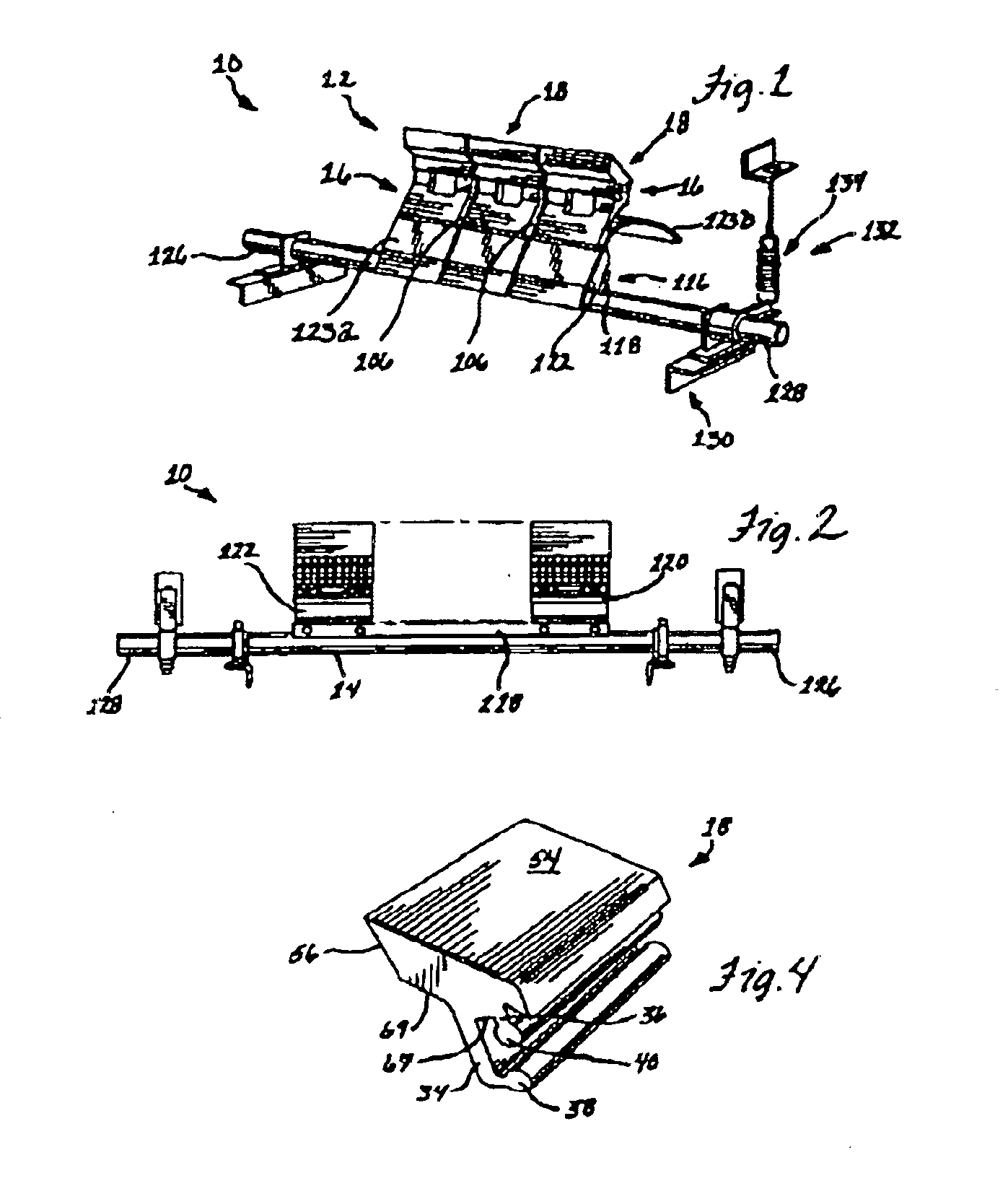
[0004]Generally, the scraper member will be used with a conveyor belt cleaner apparatus that employs an elongate rigid support member for mounting a plurality of scraper members in side-by-side orientation for scraping across the lateral width of the belt surface. With the two-part scraper blades herein, the base members can have a narrower width than the scraper members releasably connected thereto. In this manner, side ends of the adjacent scraper members can be in close-fitting or engaging relation with each other without encountering interference from the associated base members such as during installation of the scraper blades to the support member. The narrower base members also allow for lower cost manufacture thereof as the tolerances do not need to be as high since there are to be gaps between adjacent base members extending across the belt and along the support member therefor. The lateral gaps between the base members also provide spaces for material to fall through thus avoiding material build-up in the areas around and along the base members.
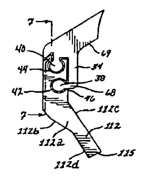
[0007]To this end, the arcuate
cam protrusion and corresponding
detent seat or recess are disposed toward one lateral end of the blade members. This
detent end can be the trailing
insertion end of the scraper member so that the opposite leading end of the scraper member is inserted first. In this way, the protrusion does not cause interference with the sliding action between the scraper and base members during scraper blade assembly until the scraper member projection is almost fully slid into its corresponding recess in the base member. In addition, a ramped lead-in surface can be provided adjacent the
detent arcuate recess for camming against the protrusion as it is inserted into the projection recess in the base member. It will be understood that the formation of the interengaging projections and recesses and the detent protrusion and recess on the scraper and base members can be substantially reversed from that in the preferred form described herein.
[0008]In the preferred form, the scraper member projections include mounting arms having enlarged ends, and the recesses in the base member include access slot portions and enlarged portions for slidingly receiving the mounting arms and their enlarged ends therein. With the projections received in the slotted recesses, the base member will provide resistance to shifting of the scraper during conveyor belt cleaning operations via wall portions thereof extending below and up around along either side of at least one of the ends of the mounting arms, and preferably both of the ends of the mounting arms.
[0010]The scraper member can also be provided with a lower, outer lip extension portion that projects about the upper, outer portion of the base member. The lip portion minimizes access of material to the joint interface between the scrapper base members and thus material build-up therein that could make removal of the scraper member from the base member extremely difficult. Accordingly, material scraped off the belt will slide down the outer surface of the scraper member down beyond the top of the base member, and then off the scraper blade so that this material does not have access to the scraper member projections or base recesses therefor.
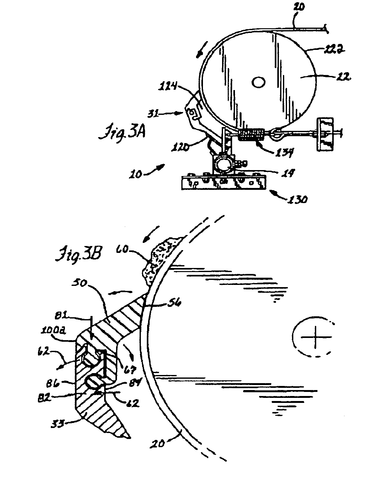
[0012]In addition, the scraper and base members are preferably configured to extend from their interface in an inward direction with the scraper member extending generally toward the belt or
pulley about which the belt extends. With this configuration, the scraper tip end portion is in engagement with the belt and the base member will have its lower section extending spaced from the belt generally tangentially thereto. In this manner, there is a clearance spacing between the scraper blade and belt that allows the tip end portion to wear back toward the blade and its joint interface between the scraper member and base member thereof.
