
Multimode modulator employing a phase lock loop for wireless communications

Inactive Publication Date: 2005-08-02
NXP USA INC
View PDF2 Cites 76 Cited by
  • Summary
  • Abstract
  • Description
  • Claims
  • Application Information

AI Technical Summary

Benefits of technology

[0008]The modulator of the present invention uses the output of a phase lock loop (PLL) to drive the power amplifier (PA). Because of the continuous phase of the PLL, the frequency spectrum of the PLL output contains very low spurious power. The amplitude information is added by modulation of the PA output, thereby synthes

Problems solved by technology

Both components are expensive, and both cause low power efficiency.

Method used


Image

  • Multimode modulator employing a phase lock loop for wireless communications
  • Multimode modulator employing a phase lock loop for wireless communications
  • Multimode modulator employing a phase lock loop for wireless communications

Examples


first embodiment

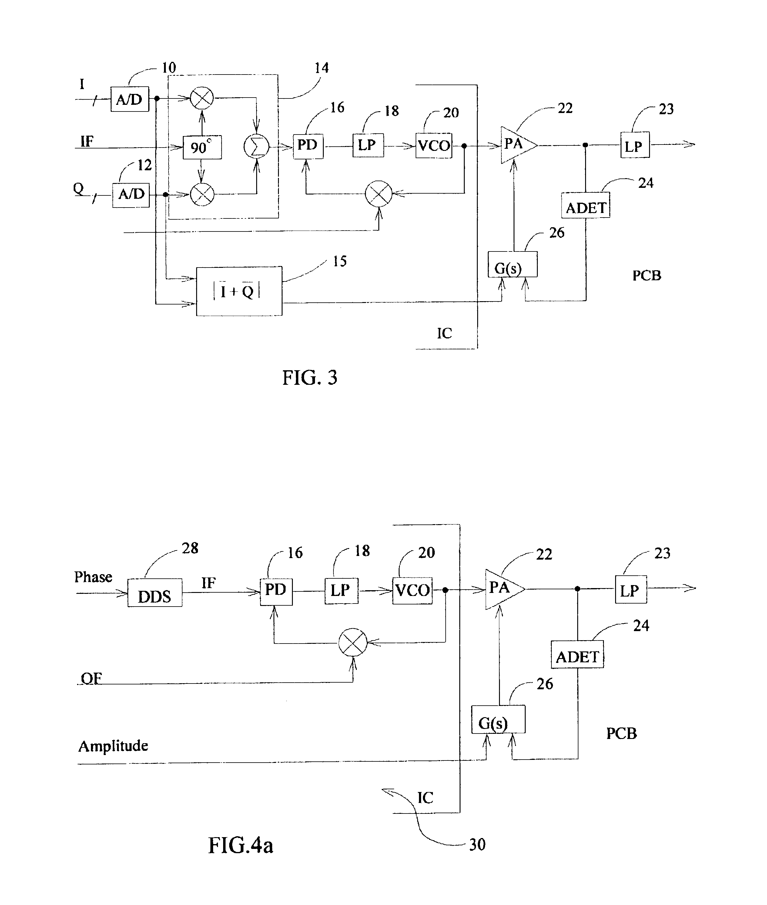
[0021]Referring to the drawings, FIG. 3 illustrates the invention. In this embodiment, the I / Q baseband vectors are used to create a precise phase-modulated intermediate carrier frequency (IF) by the means of a quadrature modulator employing analog to digital converters (A / D) 10 and 12 and phase shift architecture 14. The resulting IF from the quadrature modulator then feeds the reference phase input of phase detector (PD) 16 of a PLL. The PD output signal is conditioned by low pass filter (LP) 18. The oscillator frequency (OF) signal is mixed in the feedback loop and the voltage controlled oscillator (VCO) 20 output produces an up-converted frequency that is the sum of IF+OF, and preserves the original phase information of the I / Q signals. This signal then drives a PA 22. A non-linear PA is used with a low-pass harmonic filter 23, instead of a more expensive high order band pass filter to take advantage of the PLL's purer output spectrum.

[0022]The amplitude information of the input...

second embodiment

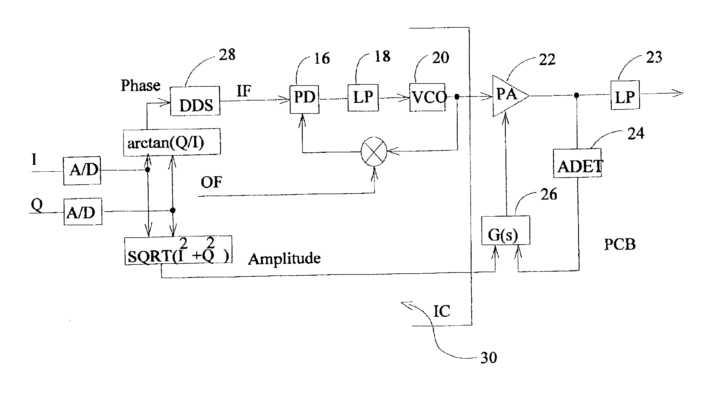
[0024]FIG. 4a shows the present invention better suited for silicon implementation. In the embodiment shown, the I / Q vectors are not used at all, thus eliminating the requirement for the A / D converters for the I / Q analog signal. The Phase-amplitude information is used in polar form, i.e. the phase angle and magnitude. A direct-digital synthesizer (DDS) 28 receives the Phase signal and generates the IF signal provided to the PLL elements (PD 16, LP 18 and VCO 20).

[0025]FIG. 4b shows the second embodiment wherein the DDS is replaced with a pulse width modulator (PWM) 28′ to provide digital synthesis of the phase to create the IF signal for the PLL. In another alternate embodiment shown in FIG. 4c, a second PLL 28″ is used in place of the DDS. The DDS or the alternatives of a PWM or second PLL and the PD, LP and VCO components of the PLL are contained on integrated circuit (IC) 30.

[0026]The embodiment of FIG. 5 enhances the cost reduction possible with the present invention by integrat...


PUM


Abstract

A phase-amplitude modulator for mobile communications employs a phase lock loop as an input to a nonlinear power amplifier providing phase information with amplitude information used to modulate the power amplifier output to synthesize phase-amplitude for the RF transmission signal.

Description

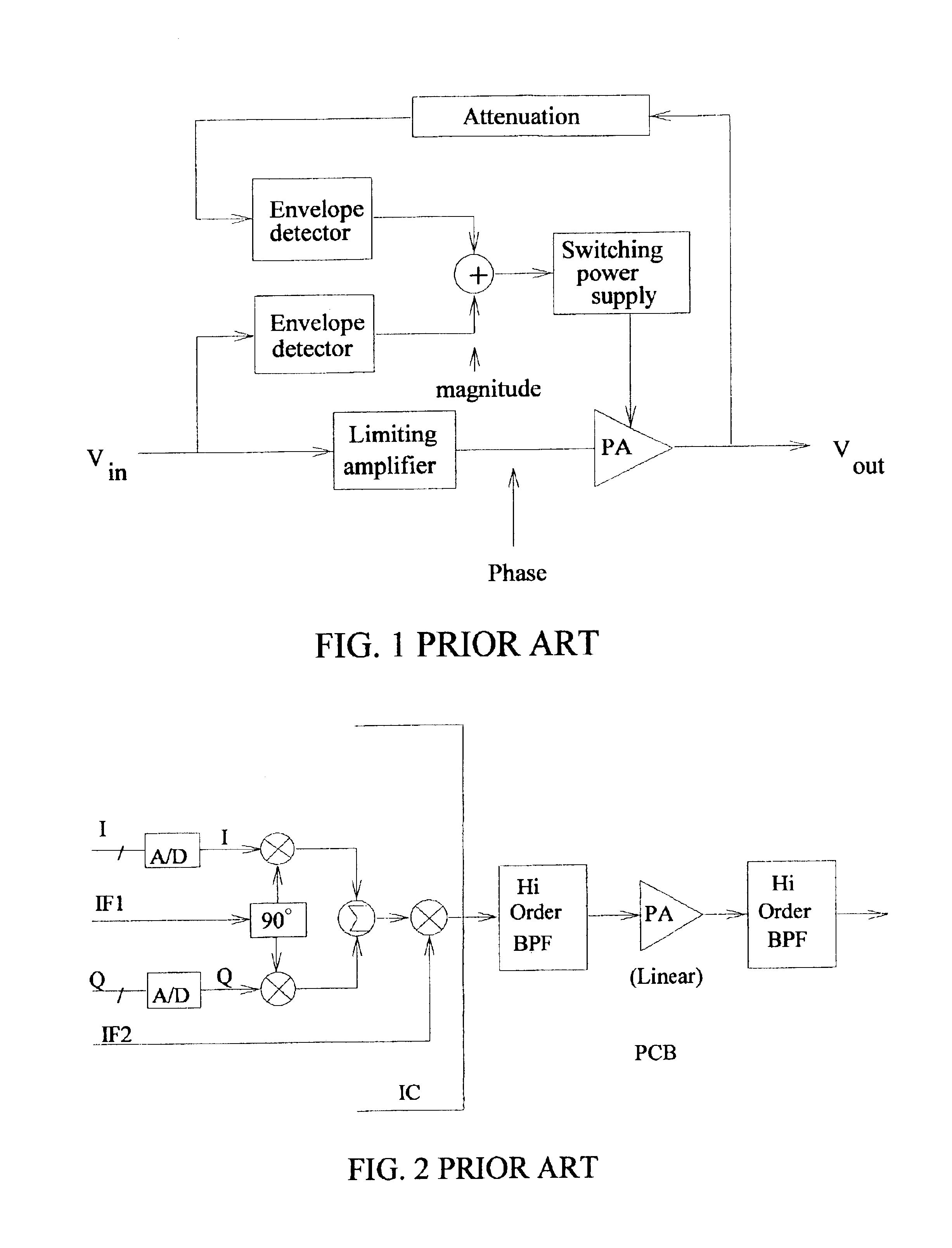
CROSS-REFERENCE TO RELATED APPLICATIONS[0001]This application claims priority of the Provisional Application Ser. No. 60 / 387,234 of the same title filed on Jun. 7, 2002.BACKGROUND OF THE INVENTION[0002]1. Field of the Invention[0003]This invention relates generally to the field of modulators for Phase Amplitude Modulation (such as QAM or QPSK) transmission signal generation. More particularly, the invention provides a Phase-Amplitude modulator using a phase lock loop (PLL) to drive the power amplifier (PA) with phase and amplitude provided by either quadrature or polar input signals resulting in a low-cost, high power efficiency transmission solution for wireless communications.[0004]2. Description of Related Art[0005]As early as the 1950's, an “Envelop Elimination & Restoration” scheme was practiced in transmitter technology, mainly to raise the RF power amplifier efficiency. This is described in detail by Leenaerts, et al (Circuit Design for RF Transceivers, ISBN 0-7923-7551-3). T...

Claims


Application Information

Patent Timeline
IPC IPC(8): H03C3/00H03C3/09
CPCH03C3/0966H03C3/0983
Inventor LIU, DONGTAI
Owner NXP USA INC
Learn More