
Machine tool with a feature for preventing a thermal deformation

a technology of machine tools and features, applied in the field of machine tools, can solve the problems of reducing machining accuracy, thermal deformation, and temperature differences between each part of the machine tool, and achieve the effect of improving the accuracy of machining a workpiece by the machine tool, and preventing the thermal deformation of the column

Inactive Publication Date: 2005-08-02
MAKINO MILLING MASCH CO LTD
View PDF18 Cites 14 Cited by
  • Summary
  • Abstract
  • Description
  • Claims
  • Application Information

AI Technical Summary

Benefits of technology

[0007]The present invention is directed to solve the above-described problems of the prior art and the objective of the invention is to provide a machine tool with a feature, for preventing the thermal deformation, which can evenly maintain the temperature of each part of a column and a workpiece mount for mounting a workpiece of the machine tool even if there are changes in a temperature in a factory or temperature differences are generated in the factory.
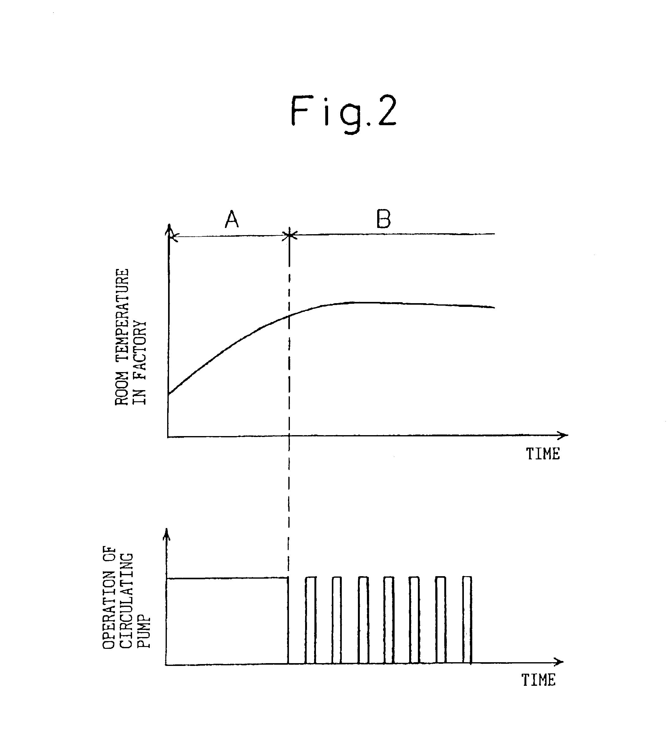
[0008]Further, the objective of the present invention is to provide a machine tool, with a feature for preventing the thermal deformation, which allows control in which the time for supplying and circulating a liquid to an internal space define in the column and the workpiece mount is changed depending on the temperature distribution in the factory.
[0009]Further, the objective of the present invention is to provide a machine tool, with a feature for preventing the thermal deformation, which can evenly maintain the temperature of each part of the column and the workpiece mount of the machine tool and can reduce the energy consumption.

Problems solved by technology

Such changes in the temperature and the temperature distribution where a machine tool is installed result in temperature differences between each part of the machine tool, such as the front, back, upper and lower portions of a column or a workpiece mount.
Therefore, the temperatures of the respective front, rear, top and bottom portions of the column cannot be the same, which results in a thermal deformation to reduce the machining accuracy.
Therefore, a complex and large apparatus is required.
Therefore, there is a problem that the energy consumption is large.

Method used


Image

  • Machine tool with a feature for preventing a thermal deformation
  • Machine tool with a feature for preventing a thermal deformation
  • Machine tool with a feature for preventing a thermal deformation

Examples


Embodiment Construction

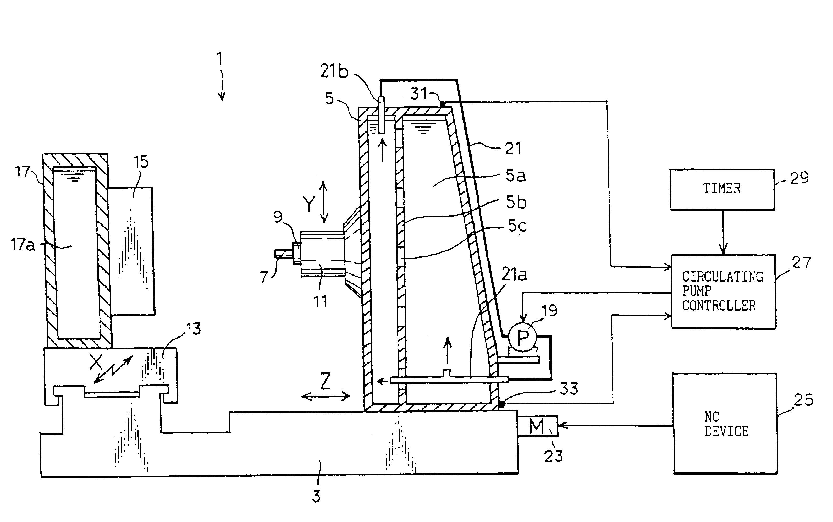
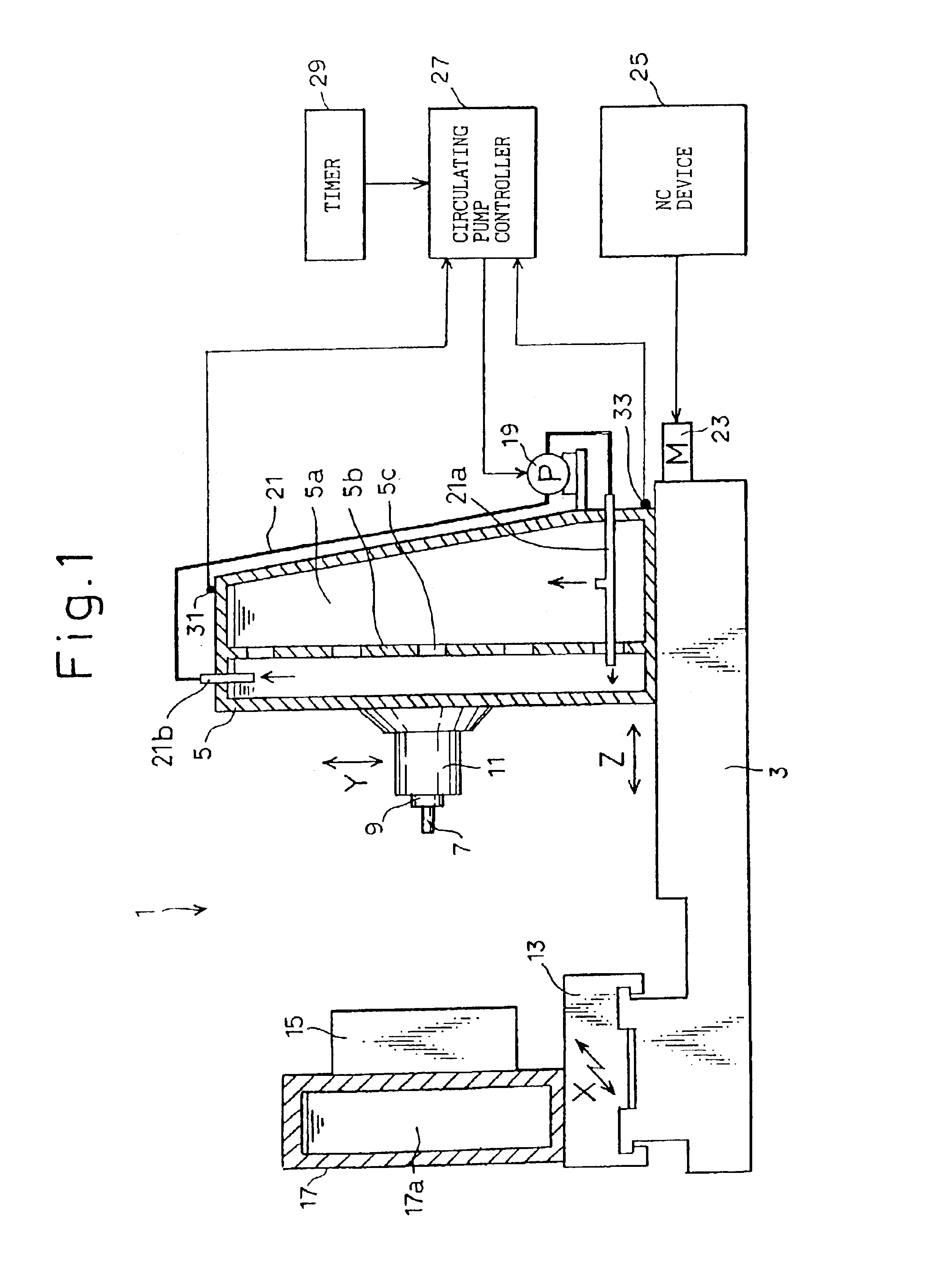
[0024]First, a preferable embodiment of a machine tool according to the present invention will be described with reference to FIG. 1. In this embodiment, a horizontal machining center is described as an example. However, the present invention is not limited to this configuration and can be applied to, for example a vertical machining center, a milling machine, a grinder, a lathe, an electrical diesinking discharge machine and a wire electrical discharge machine.

[0025]A horizontal machining center 1 includes a bed 3 defining a base, a column 5 provided on the bed 3 in the reward portion thereof to move in Z-axial direction (left-and-right direction in FIG. 1), a spindle head 11, provided on the front face of the column 5 to move in Y-axial direction (top-and-bottom direction in FIG. 1), for rotationally supporting a spindle 9 to which a tool 7 is fitted, a table provided on the bed 4 in the forward portion thereof to move in X-axial direction (perpendicular to the page of FIG. 1) and...


PUM

PropertyMeasurementUnit
temperatureaaaaaaaaaa
thermal deformationaaaaaaaaaa

Abstract

A machine tool 1 comprises a spindle head 11 for supporting a spindle 9 to which a tool 7 is fitted, a column 5 for supporting the spindle head 11 and a table 13 for mounting a workpiece 15, and machines the workpiece 15 by relatively moving the tool and the workpiece. A cavity 5a is defined in the column so that a liquid can be circulated. A liquid pump 19 is provided for circulating the liquid into the cavity 5a. A circulating pump controller 27 is provided for controlling the circulation of the liquid by activating and deactivating the liquid pump 19. By circulating the liquid into the cavity 5a of the column 5, the temperature of each part of the column 5 is evenly maintained to prevent the thermal deformation of the column 5.

Description

TECHNICAL FIELD[0001]The present invention relates to a machine tool which machines a workpiece by relatively moving a tool and the workpiece, and in particular to a machine tool which is improved to prevent a thermal deformation by evenly maintaining the temperature of each part of machine tool such as a column and a workpiece mount for mounting the workpiece.BACKGROUND ART[0002]Generally, an air conditioner is provided in a factory within which a machine tool is installed. Once the air conditioner is activated, the room temperature in the factory changes to gradually settle to a certain temperature. In particular, when the room temperature changes, temperature differences are generated between the high places and the lower places in the factory. Further, differences in the temperature occur between areas near the outlet of the air conditioner, the doors and / or the windows of the factory and the areas distant therefrom. The magnitudes of the temperature differences and the temperat...

Claims


Application Information

Patent Timeline
Patent Type & Authority Patents(United States)
IPC IPC(8): B23Q11/14B23Q1/00B23Q1/01B23Q1/72
CPCB23Q1/015B23Q11/148Y10T409/304032Y10T409/30868Y10T409/303976Y10T409/309016
Inventor MUTO, AI
Owner MAKINO MILLING MASCH CO LTD
Learn More