Cable lock assembly to ensure stable linear movement of the latch bolt

Inactive Publication Date: 2005-08-02
KUO LAMBERT
View PDF7 Cites 34 Cited by
  • Summary
  • Abstract
  • Description
  • Claims
  • Application Information

AI Technical Summary

Benefits of technology

[0011]The main objective of the present invention is to provide a lock assembly that is durable and reliable.

Problems solved by technology

However, friction between the push pin (521) and the spiral groove (54) causes the push pin (521) and the spiral groove (54) to wear.
Specifically, the push pin (521) wears down and eventually shears off causing the lock assembly to fail.
Uneven wear of the spiral groove (54) causes the lock assembly to operate erratically.
Therefore, the conventional lock assembly is neither reliable nor durable and these problems can lead to considerable frustration where a user is unable to unlock the locked item.

Method used


Image

  • Cable lock assembly to ensure stable linear movement of the latch bolt
  • Cable lock assembly to ensure stable linear movement of the latch bolt
  • Cable lock assembly to ensure stable linear movement of the latch bolt

Examples


Embodiment Construction

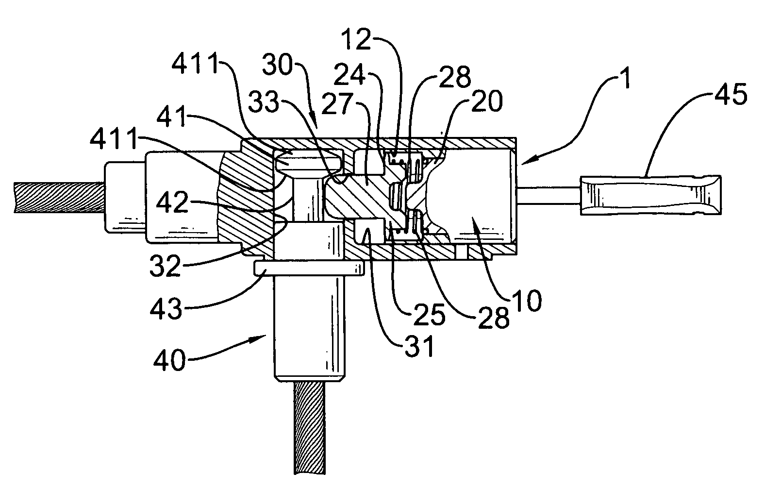
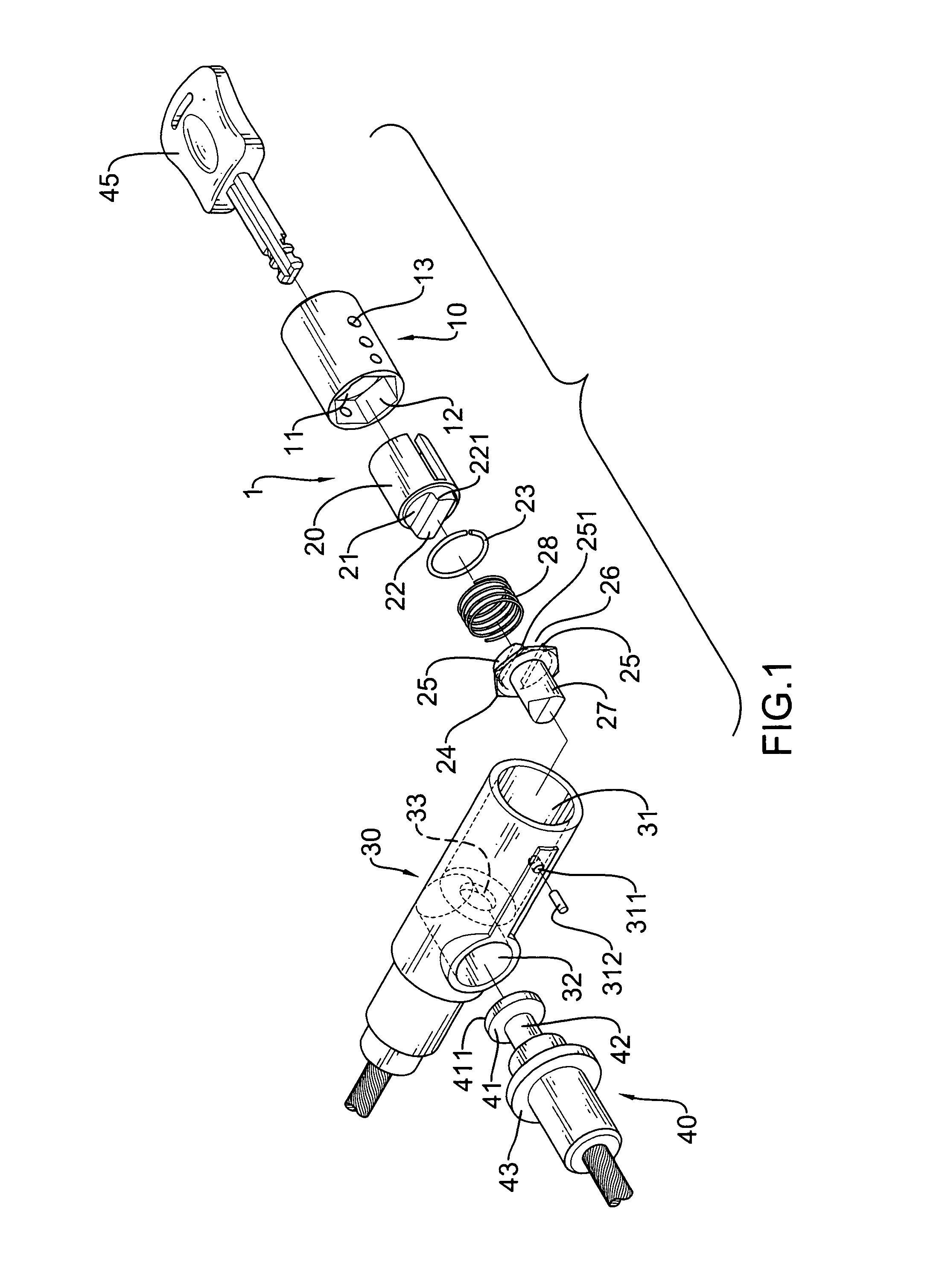
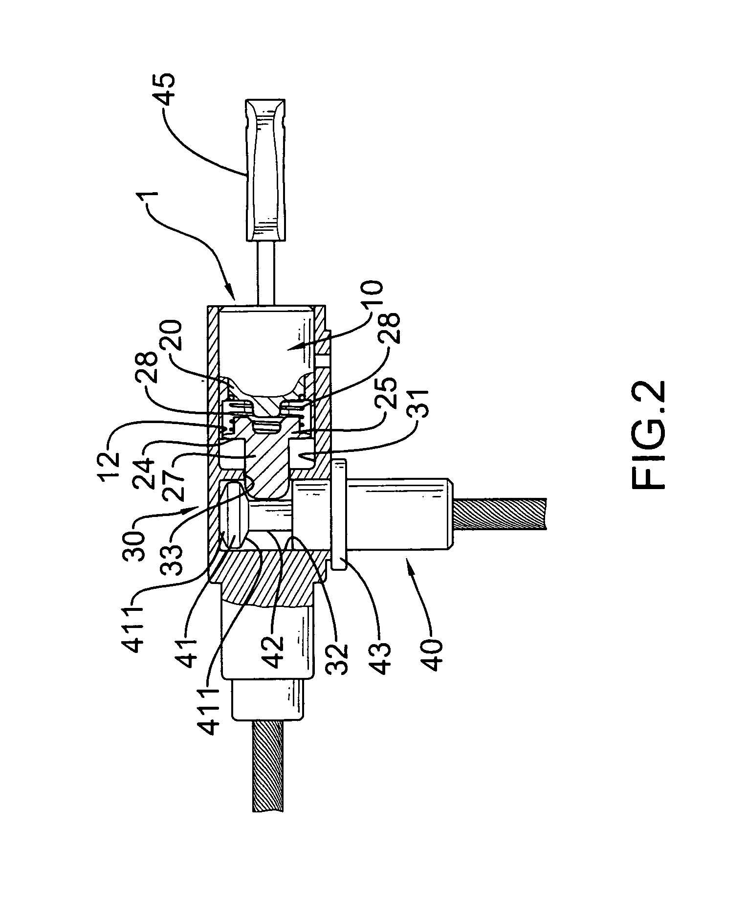
[0022]With reference to FIG. 1, a first embodiment of a lock assembly (1) in accordance with the present invention comprises a casing (30), a cylinder assembly (10), a rotary bolt driver (20) and a shank (40).

[0023]The casing (30) is cylindrical and has a longitudinal chamber (31), a locking-pin hole (311), a locking pin (312) and a transverse chamber (32). The longitudinal chamber (31) is formed at the distal end of the casing (30) and has an open end as an access (not numbered) for receiving therein the rotary bolt driver (20) and the cylinder assembly (10), and a bolt hole (33). The locking-pin hole (311) is defined radially through the outer surface of the casing (30) and in the sidewall of the longitudinal chamber (31). The bolt hole (33) is formed through the inside end of the longitudinal chamber (31). The transverse chamber (32) is formed in the casing (30) perpendicular to the longitudinal chamber (31) and near the inside end of the longitudinal chamber (31) to communicate ...


PUM


Abstract

A lock assembly includes a casing containing a cylinder assembly, a rotary bolt driver and a shank inside the casing. The rotary bolt driver has a crossbar to selectively abut two stop blocks formed on a latching disk. Thus the rotational movement of the rotary bolt driver is able to move the latching disk inside the longitudinal chamber so as to secure the shank inside the casing.

Description

BACKGROUND OF THE INVENTION[0001]1. Field of the Invention[0002]The present invention relates to a lock assembly, and more particularly to a lock assembly for a bicycle or the like to ensure smooth linear movement of the latch bolt.[0003]2. Description of Related Art[0004]With reference to FIGS. 8 and 9, a conventional lock assembly comprises a casing (60), a cylinder assembly (50) and a shank (70). The cylinder assembly (50) is mounted inside the casing (60). The shank (70) is partially inserted into the casing (60) and is held in the casing (60) by the cylinder assembly (50).[0005]The casing (60) is cylindrical and has a distal end (not numbered), a cylinder chamber (61) and a shank chamber (62). The cylinder chamber (61) is formed longitudinally in the distal end of the casing (60) and has an open outside end (not numbered), an inside end (not numbered) and a bolt hole (63). The bolt hole (63) is formed through the inside end of the cylinder chamber (61). The shank chamber (62) i...

Claims


Application Information

Patent Timeline
IPC IPC(8): E05B67/06E05B67/00
CPCE05B67/003Y10T70/483Y10T70/5009Y10T70/5872
Inventor KUO, LAMBERT
Owner KUO LAMBERT
Why Eureka
Try Eureka