
Apparatus and method for smooth cornering in a motion control system

a motion control system and apparatus technology, applied in the direction of program control, electric controllers, instruments, etc., can solve the problems of inability to achieve infinite acceleration, undesirable etc., to achieve efficient control of motion through a programmed turn, reduce or eliminate step discontinuities in velocity and/or acceleration

Inactive Publication Date: 2005-07-26
SIEMENS ENERGY & AUTOMATION INC
View PDF37 Cites 92 Cited by
  • Summary
  • Abstract
  • Description
  • Claims
  • Application Information

AI Technical Summary

Benefits of technology

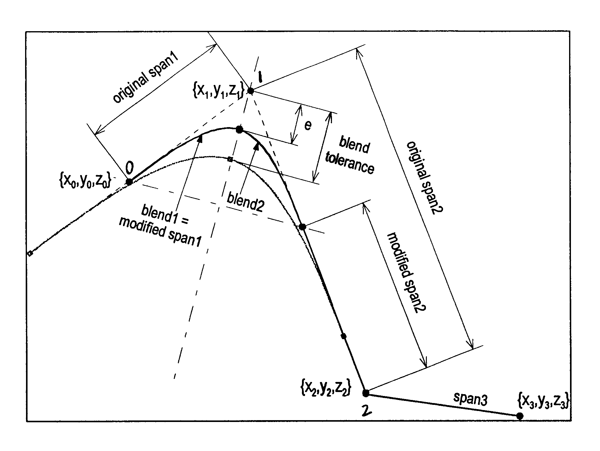
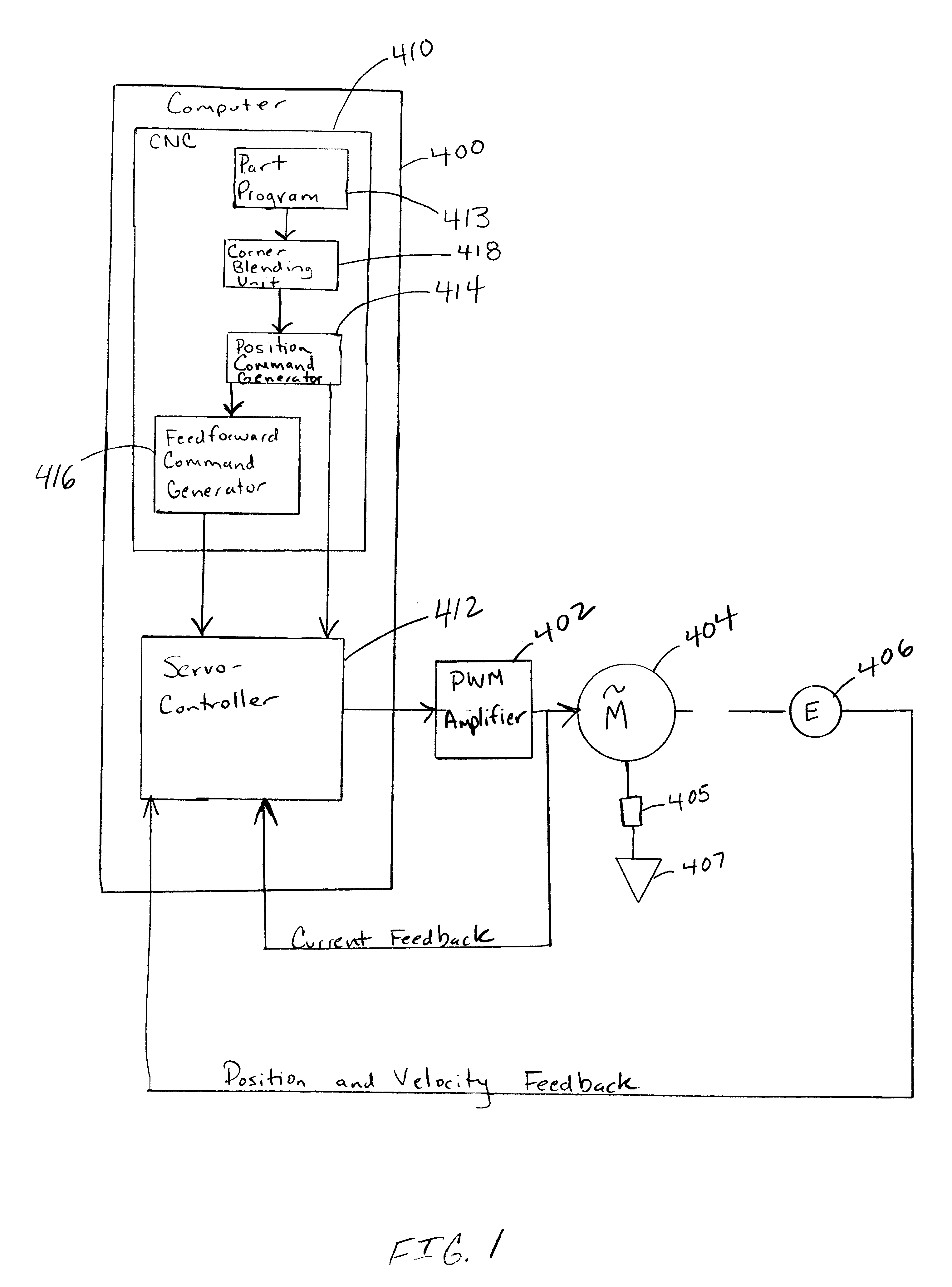
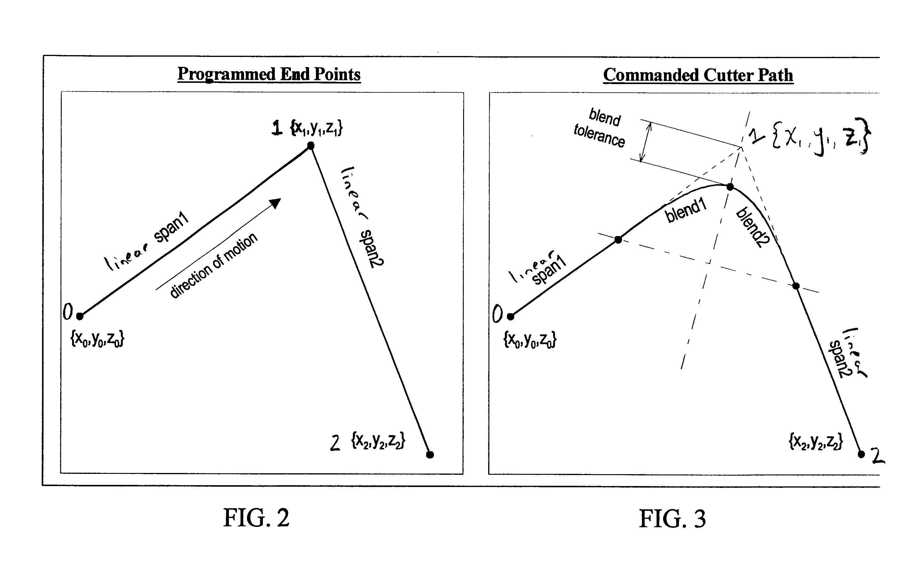
[0010]It is an object of the present invention to provide an apparatus and method which efficiently controls motion through a programmed turn or corner while reducing or eliminating step discontinuities in velocity and / or acceleration.

Problems solved by technology

However, traversing such a corner can result in a step discontinuity in the commanded velocity of the movable member.
Step discontinuities in velocity are undesirable because they can inject high frequency energy into the position control loop of a servocontroller providing the controlled motion, such that the actual motion achieved by the controller does not exactly track the command position trajectory represented by the path points.
Moreover, step discontinuities in velocity command result in a requirement of infinite acceleration in order for the controlled moveable member to actually follow the command.
Infinite (or very large and fast changes in) accelerations are never actually achieved by the movable member due to the ultimate low-pass nature of the servo loops controlling the member, thus the command is not precisely duplicated by the motion of the member.
A step discontinuity in velocity command can result in structural vibrations and wear of machine components, among other problems, such as mechanical deflection and cross-coupled axis dynamics where motion or vibration in one axis causes undesired motion or vibration on a separate axis.
In the machine tool context, these undesirable phenomena can also result in unacceptable surface finish and / or reduced accuracy of the machined part.
While it has been known that commanding a full stop at the corner point can eliminate step discontinuities in velocity, such stops are undesirable because they increase the time required to complete the motion.
Moreover, in the machine tool context, full stops can also create undesirable “dwell marks” on the workpiece.
Consequently, to avoid the speed limitations of using a full stop at corners, it has been known in the art to move through corners using some tolerable step velocity discontinuities, resulting in some tolerable amount of corner rounding.
However, such arcs can result in undesirable step discontinuity in acceleration, which can result in machine wear and poorly machined parts.

Method used


Image

  • Apparatus and method for smooth cornering in a motion control system
  • Apparatus and method for smooth cornering in a motion control system
  • Apparatus and method for smooth cornering in a motion control system

Examples


example of an exemplary embodiment

[0279]The benefits of the exemplary embodiment of the spline corner blend described herein relative to insertion of circular arcs or step velocities will be illustrated by the following example, which is illustrated by FIGS. 12-15. The example is for a case where a 5 mm X-axis move is followed by a 5 mm Y-axis move, beginning and ending in a full stop. The programmed feedrate for the move is about 2500 mm / min. The 90 degree corner formed by the two spans is traversed using three different methods: 1) spline corner blend (SCB) with feedforward enabled, 2) inserted circular arcs with feedforward enabled, and 3) step velocity at a sharp corner with feedforward disabled. The axis configuration parameters for this example are typical for a general-purpose small vertical machining center.

[0280]For the SCB case, a corner blend tolerance of about 0.5 mm has been selected in this example. For the circular arc case, an arc radius of about 1.207 mm is used, as it will cause the closest approac...


PUM


Abstract

A method and apparatus for controlling motion through consecutive linear spans that define a corner in a desired motion path, such as a motion path in a machine tool system for example, is disclosed. In one embodiment, a plurality of data points that define a desired motion path is provided, and the plurality of data points define a plurality of consecutive spans. It is determined whether two consecutive linear spans define a corner having an angle within a predetermined range, and if so, a non-linear path is determined which connects to the two consecutive linear spans with continuity in curvature. An actuator is then controlled according to the non-linear path.

Description

[0001]This application claims the benefit of U.S. Provisional Application No. 60 / 166,625, filed on November 19, 1999.TECHNICAL FIELD[0002]The present invention relates generally to equipment and processes for controlling the motion of a movable member through a programmed path, and, more specifically, to an improved apparatus and method for motion control wherein corners on the path are identified and then smoothly blended to minimize discontinuities in velocity, acceleration, and / or jerk.BACKGROUND ART[0003]In a controlled motion system, such as a CNC (computer numerical control) controlled machine tool system for example, movable machine members are moved along a programmed path by programming the motion command and specifying position coordinates on the path. Linear paths are typically defined by programming the path end points on the line, circular paths are typically defined by programming the circle end points and circle center data, and arcuate paths are typically defined by ...

Claims


Application Information

Patent Timeline
Patent Type & Authority Patents(United States)
IPC IPC(8): G05B19/41G05B19/4103G05B19/00
CPCG05B19/00G05B19/4103G05B2219/34098G05B2219/34135G05B2219/34142G05B2219/34143G05B2219/49164
Inventor YUTKOWITZ, STEPHEN J.
Owner SIEMENS ENERGY & AUTOMATION INC
Learn More