
Hand trolley with winch operated lifting carriage

a technology of lifting carriage and hand trolley, which is applied in the field of hand trolley, can solve the problems of operator injury, operator sprain, and operator ergonomically unsound position when cranking the winch, and achieve the effect of facilitating clear and ergonomically sound movement of the handl

Inactive Publication Date: 2005-07-26
MIDDLEBY ROBERT J
View PDF29 Cites 56 Cited by
  • Summary
  • Abstract
  • Description
  • Claims
  • Application Information

AI Technical Summary

Benefits of technology

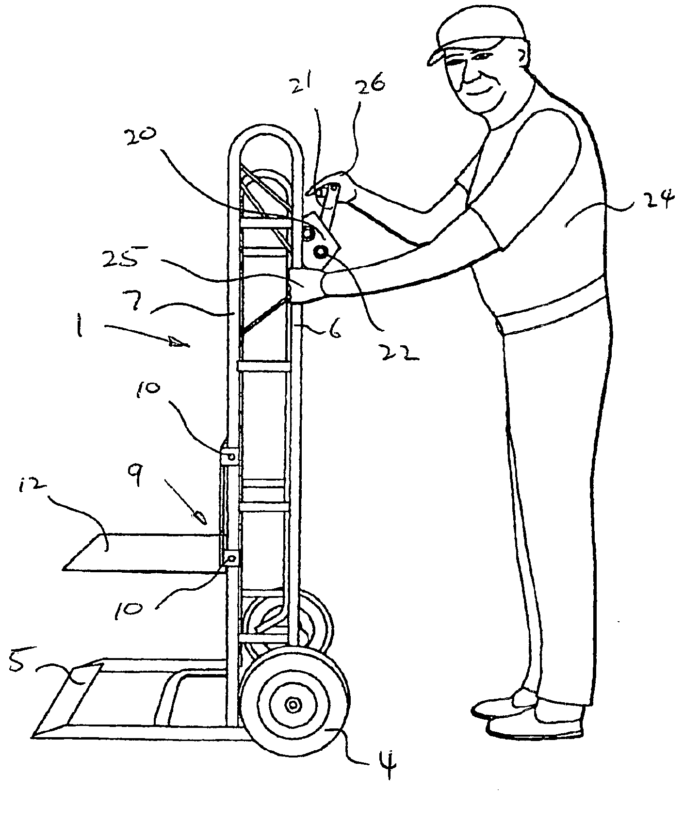
[0013]Preferably the winch operating handle is extended outwardly beyond the load support chassis to facilitate clear and ergonomically sound movement of the handle.

Problems solved by technology

It is a disadvantage of conventional hand trolleys of this type, that although they are very suited to moving a heavy load from one location at ground or floor level to another location at the same level, they do not assist the operator in picking up or setting down a load to an elevated position.
Attempts have been made to overcome this problem by providing hand trolleys with lifting tynes that can be raised using a hand winching mechanism when the trolley is in the upright position, but such constructions have suffered from the disadvantage that the winching mechanisms are typically placed in a mid-height position on the underside or rearside of the trolley chassis with the winch cranking axis perpendicular to the axle supporting the wheels.
This not only restricts the height to which the lifting tynes can be raised but which also results in an ergonomically unsound position for an operator cranking the winch.
This leads to the danger of injury to the operator and furthermore a trolley of this design is inherently unstable while the load is being raised making it prone to toppling and either injuring the operator or damaging the load.

Method used


Image

  • Hand trolley with winch operated lifting carriage
  • Hand trolley with winch operated lifting carriage
  • Hand trolley with winch operated lifting carriage

Examples


Embodiment Construction

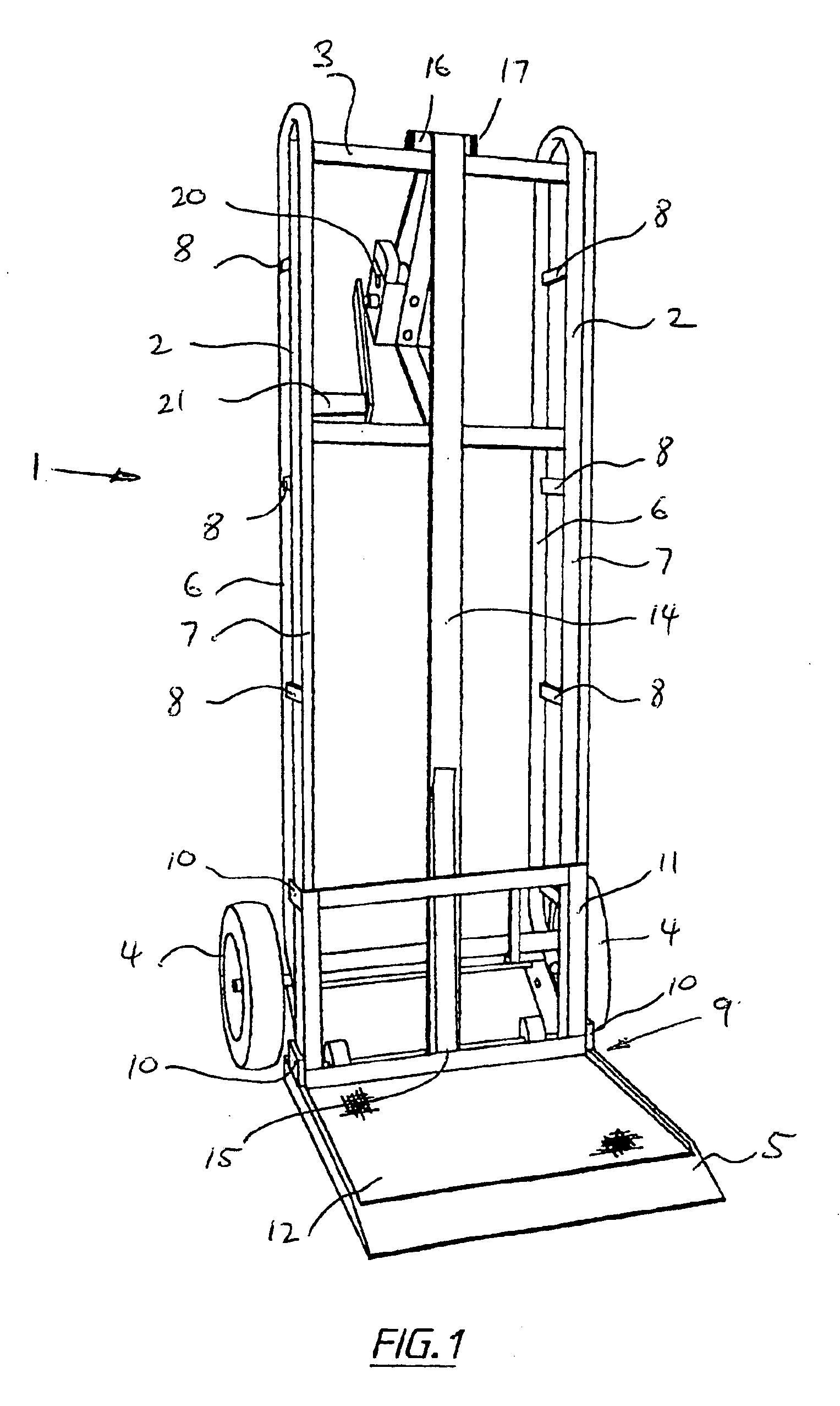
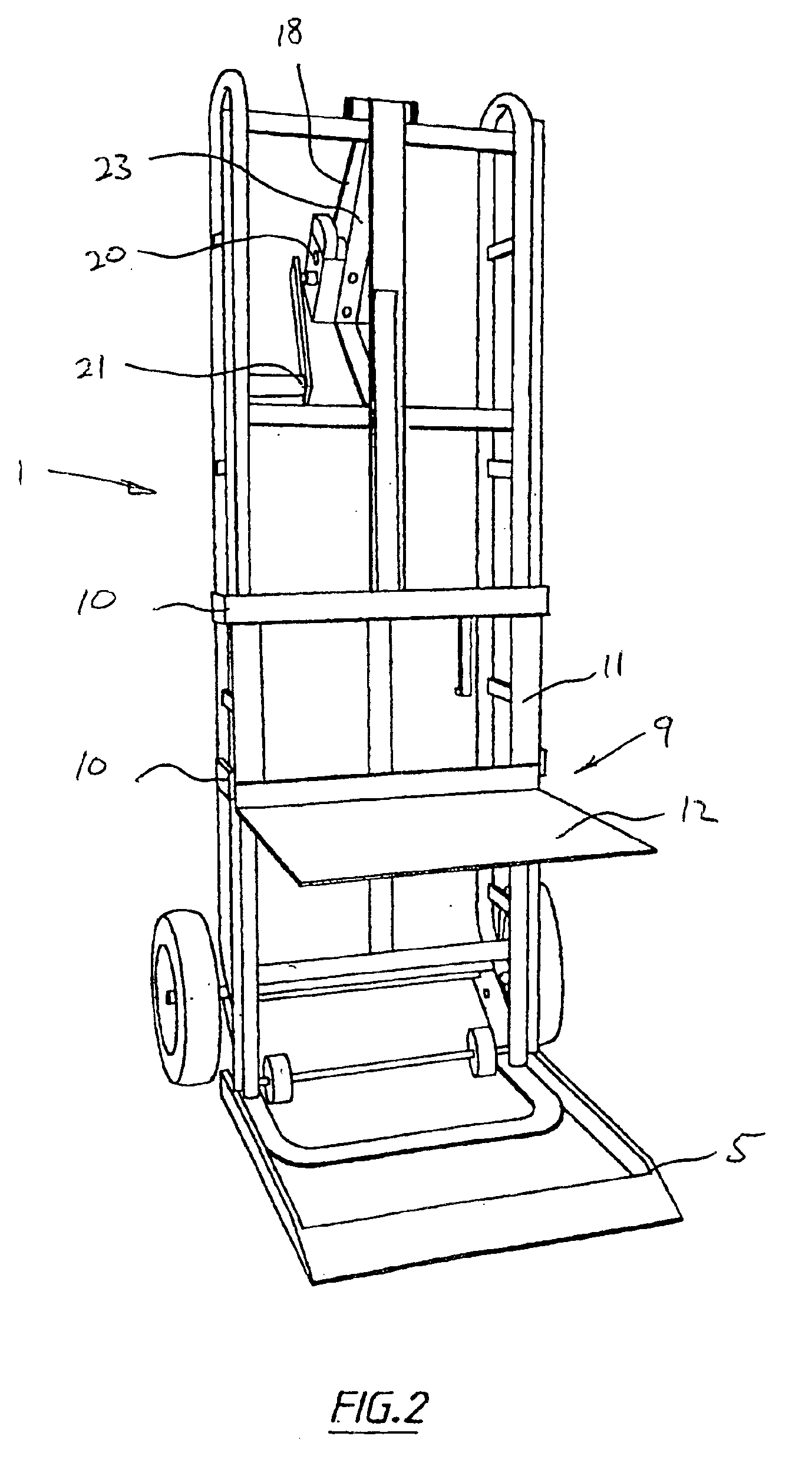
[0021]In the preferred form of the invention, a hand trolley is constructed by modifying a well known type of trolley whose overall construction is generally shown at 1, although it will be appreciated that the trolley can be designed in other forms rather than modifying an existing construction.

[0022]The hand trolley includes a load supporting chassis typically including a pair of upright side frames 2 interconnected at their upper ends by a transverse rail 3 and being provided with a pair of support wheels 4 located toward the lower end of the chassis. The wheels 4 are adjacent a base platform 5 extending substantially at right angles to the side frame 2. The upright side frames may each be formed from a pair of parallel tubular frame members 6 and 7 joined by struts 8 or may take any other suitable form such as a single large diameter tube or other structural member.

[0023]To form a hand trolley according to the invention, a load lifting carriage 9 is provided slideably mounted to...


PUM


Abstract

A hand trolley includes a chassis formed from side frames comprising parallel frame members, wheels and a base platform provided with a load lifting carriage having a lifting surface. The carriage can be raised from a low position on the base platform to an elevated position by operating a hand cranked winch with a crank handle rotatable about an axle located proximate to a hand grip on the chassis rails and parallel to the axis of the wheels. The positioning and orientation of the crank handle allows correct ergonomic use by an operator who can grip the trolley chassis with one hand while controlling and operating the crank handle in an ergonomically sound position.

Description

[0001]This application is the U.S. national phase of international application PCT / AU03 / 00251, filed Feb. 28, 2003, which designated the U.S., the entire contents of which are hereby incorporated by reference.FIELD OF THE INVENTION[0002]This invention relates to a hand trolley and has been devised particularly though not solely for the lifting of heavy objects.BACKGROUND OF THE INVENTION[0003]It is well known to provide hand trolleys for the lifting of heavy objects from a location, typically at ground or floor level, and the transportation of those objects to a different location. Such hand trolleys typically have a pair of support wheels located toward one end of an elongate chassis with a hand grip at the opposite end of the chassis and a load support platform extending outwardly from the chassis adjacent but on the opposite side to the wheels. In use, the operator pushes the load support platform under the load to be lifted until an upright portion of the load rests against the ...

Claims


Application Information

Patent Timeline
IPC IPC(8): B62B1/10B62B1/00B66F9/00B66F9/02
CPCB62B1/10B66F9/02B62B2203/10
Inventor MIDDLEBY, ROBERT J.
Owner MIDDLEBY ROBERT J
Learn More