
Drop ball catcher apparatus

a technology of catching apparatus and drop ball, which is applied in the direction of fluid removal, sealing/packing, and wellbore/well accessories, etc. it can solve the problems of not taking into account the drop ball itself, and wasting valuable time and resources. , to achieve the effect of reducing the proliferation of downhole debris

Inactive Publication Date: 2005-07-26
WEATHERFORD TECH HLDG LLC
View PDF15 Cites 87 Cited by
  • Summary
  • Abstract
  • Description
  • Claims
  • Application Information

AI Technical Summary

Benefits of technology

[0015]It is an object of the drop ball catcher apparatus of the present invention to minimize the proliferation of downhole debris caused by ejecting the drop ball into the wellbore.

Problems solved by technology

While current drop ball systems—such as those described above—provide a reliable means for actuating downhole tools, these systems do not account for the drop ball itself once the tool has been activated.
However, at the bottom of the wellbore, the drop ball becomes an obstacle for the drill bit to break up as drilling operations are resumed.
This of course expends valuable time and resources.

Method used


Image

  • Drop ball catcher apparatus
  • Drop ball catcher apparatus
  • Drop ball catcher apparatus

Examples


Embodiment Construction

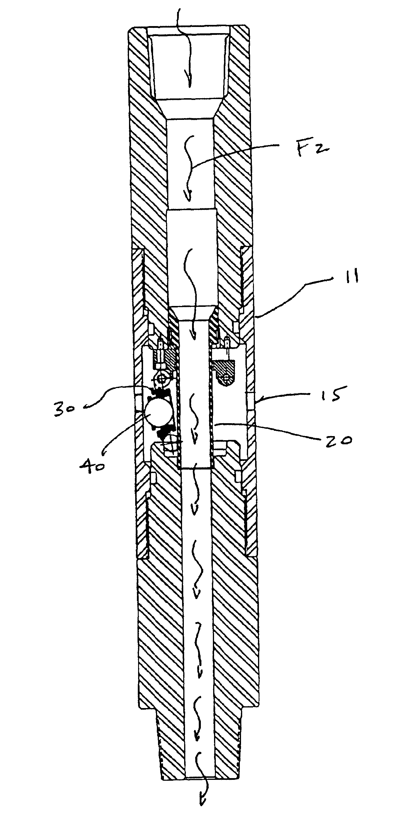
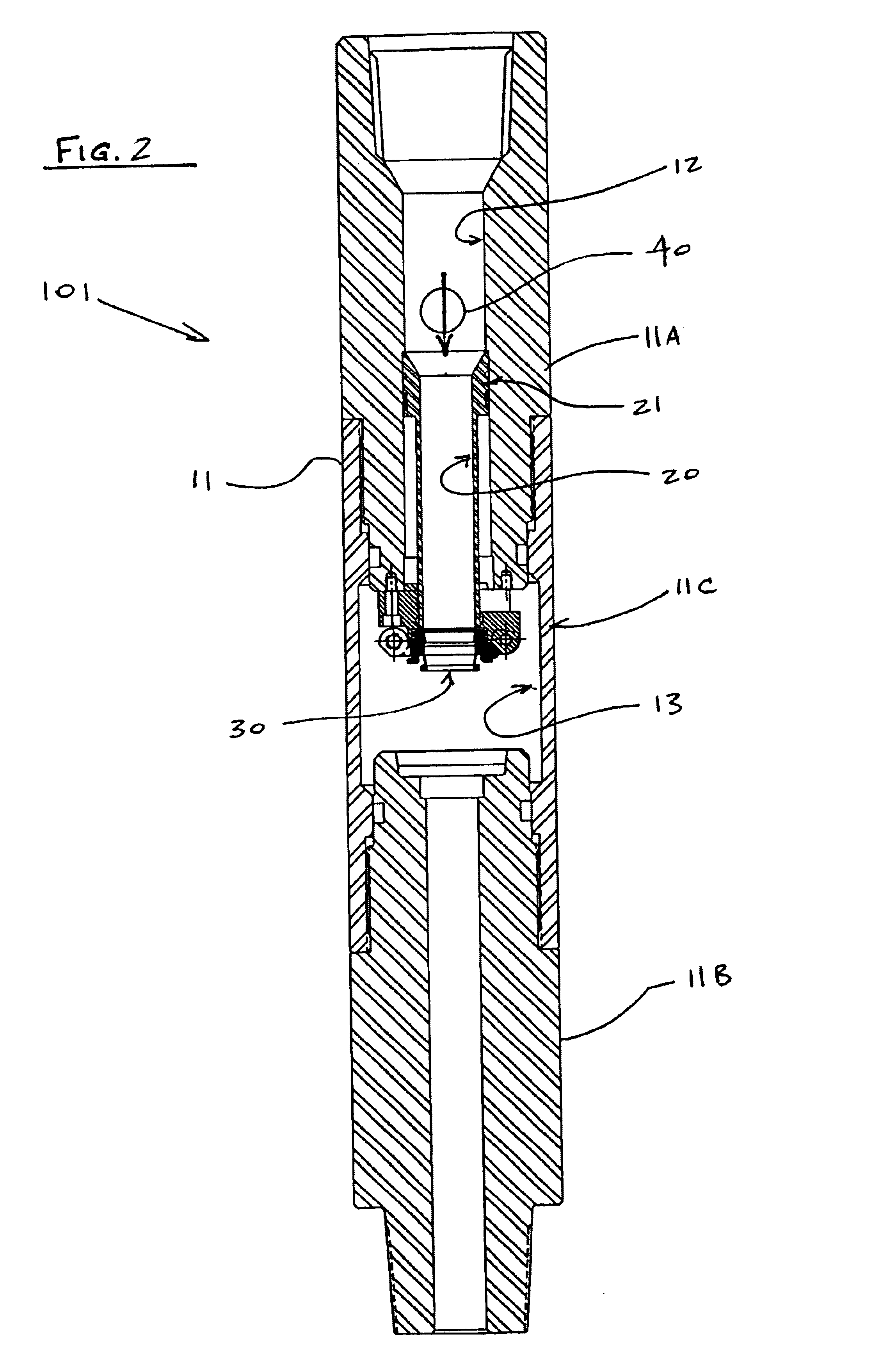
[0028]A description of certain embodiments of the present invention is provided to facilitate an understanding of the invention. This description is intended to be illustrative and not limiting of the present invention. While the drop ball catcher apparatus is described in connection with a ball-actuated diverter tool, it is intended that the drop ball catcher apparatus may be used with any ball-actuated downhole tool.

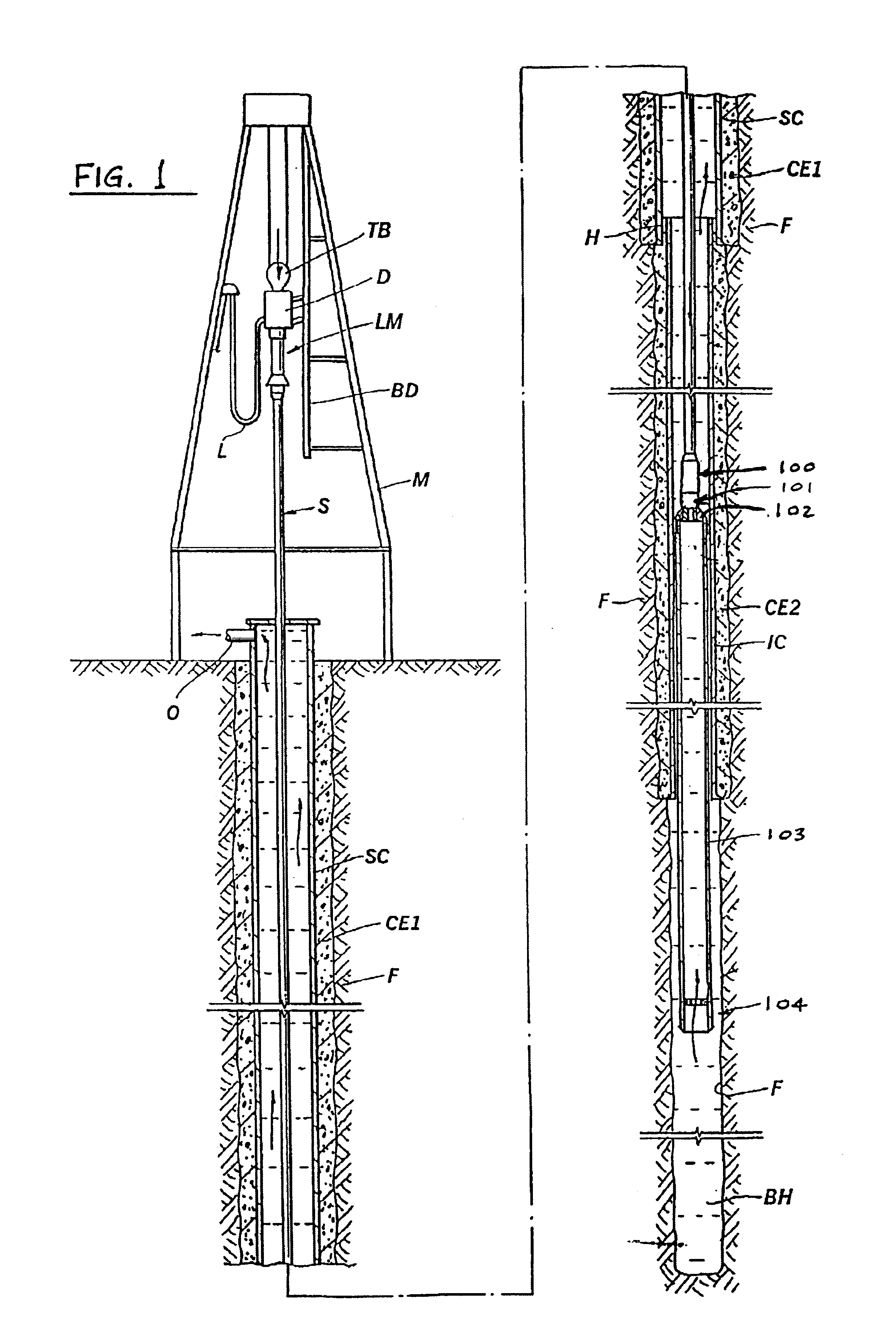
[0029]With reference first to FIG. 1, the general components of a system in which a tool in accordance with the present invention is used are illustrated. A mast M suspends a traveling block TB. The traveling block, in turn, supports a top drive TD which moves vertically on a block dolly BD. An influent drilling fluid line L supplies the top drive TD with drilling fluid from a drilling fluid reservoir (not shown). A launching manifold LM connects to a drill string S. The drill string S comprises numerous pipe elements which extend down into the borehole BH, and the num...


PUM


Abstract

A drop ball catcher apparatus for use with downhole tools in oil well drilling and installation operations. A drop ball catcher apparatus is used to receive and stow a drop ball ejected from a ball-actuated downhole tool.

Description

BACKGROUND OF THE INVENTION[0001]1. Field of the Invention[0002]The present invention relates to an apparatus for use in the oil well industry, and, more particularly, to a drop ball catcher apparatus for use with downhole tools in oil well drilling and installation operations.[0003]2. Description of the Prior Art[0004]Drop ball mechanisms are used in oil well drilling and installation operations typically to activate downhole tools. In U.S. Pat. No. 6,467,546, for example, a drop ball mechanism is disclosed for use in activating downhole tools and devices, namely: float equipment, flapper valves, squeeze tools, inflatable packers, running tools, adaptors, test tools, and the like. The drop ball apparatus of the '546 patent includes a drop ball and a yieldable ball seat. The yieldable ball seat is attached to an inner sleeve arranged within a downhole tool. The downhole tool is generally suspended in a borehole on a tubular string such as a drill string. To activate the downhole too...

Claims


Application Information

Patent Timeline
Patent Type & Authority Patents(United States)
IPC IPC(8): E21B34/00E21B23/04E21B23/00E21B34/14E21B41/00
CPCE21B23/04E21B34/14E21B41/0021E21B23/0413
Inventor ALLAMON, JERRY P.MILLER, JACK E.
Owner WEATHERFORD TECH HLDG LLC
Learn More