
Circuit for conditioning a supply at the maximum power point

a technology of supply circuit and power point, applied in the field of power supply operation, can solve problems such as complex implementation of solutions, affecting the reliability of the electrical power supply subsystem, and particularly acute problems

Inactive Publication Date: 2005-07-19
ALCATEL LUCENT SAS
View PDF7 Cites 235 Cited by
  • Summary
  • Abstract
  • Description
  • Claims
  • Application Information

AI Technical Summary

Benefits of technology

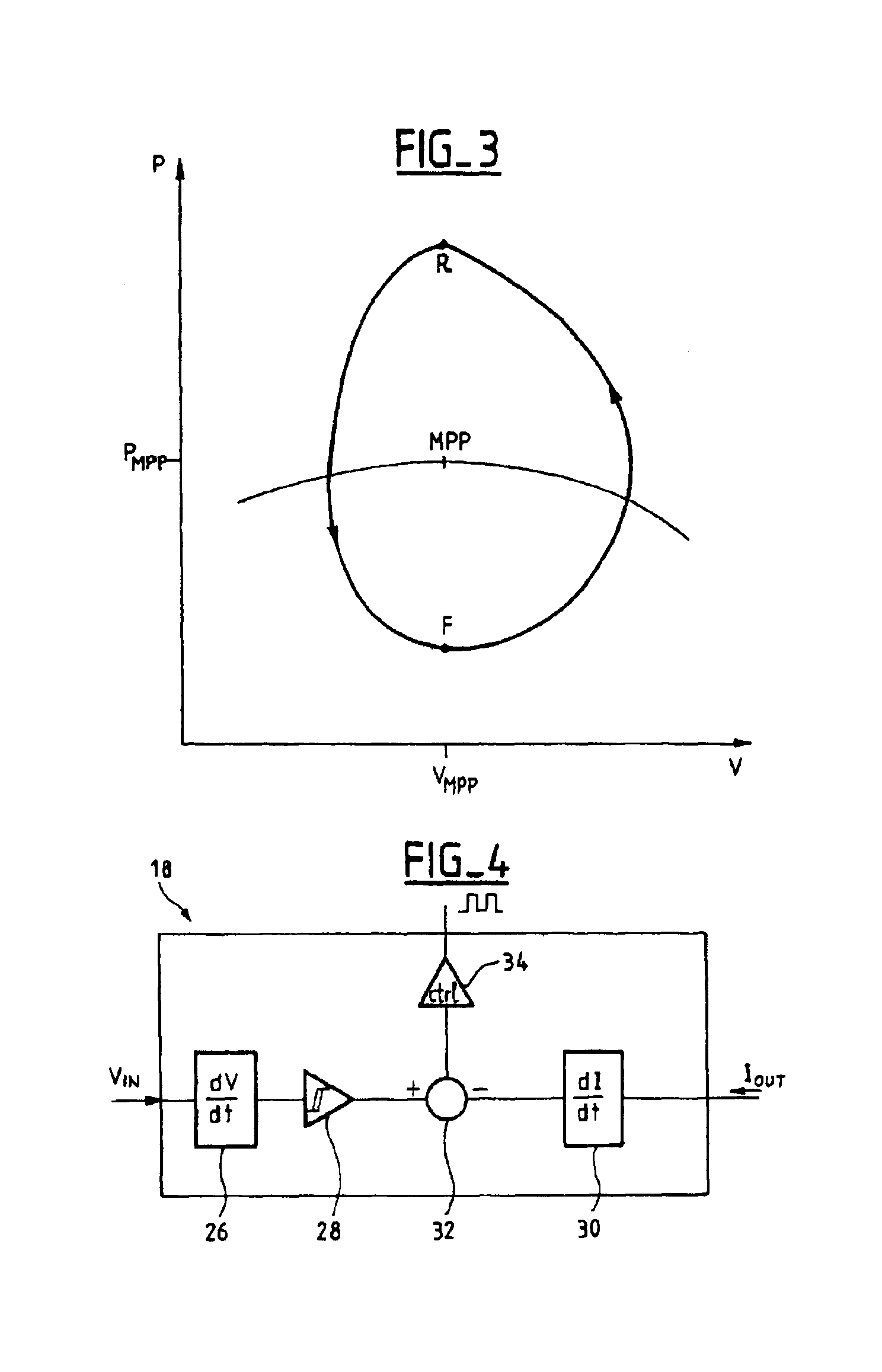
[0018]Consequently, one embodiment of the invention provides a circuit for conditioning a power supply whose graph of the power supplied as a function of the voltage at the terminals of the power supply features a maximum, the circuit comprising a DC/DC converter with an input to which power is supplied by the power supply and an output from which power is supplied to a load and a control circuit for controlling the converter in accordance with a power set point applied to the co

Problems solved by technology

This problem is particularly acute in the case of solar generators used on satellites.
These solutions are complex to implement.
They lead to centralizing control of maximum power point tracking of the various solar generators, and this centralization affects the reliability of the electrical power supply subsystem and is incompatible with maximum power points at different voltages in different sections of the solar generator.
Furthermore, these solutions use the direct components of the currents and / or voltages, which are not characteristic of maximum power point tracking.

Method used


Image

  • Circuit for conditioning a supply at the maximum power point
  • Circuit for conditioning a supply at the maximum power point
  • Circuit for conditioning a supply at the maximum power point

Examples


Embodiment Construction

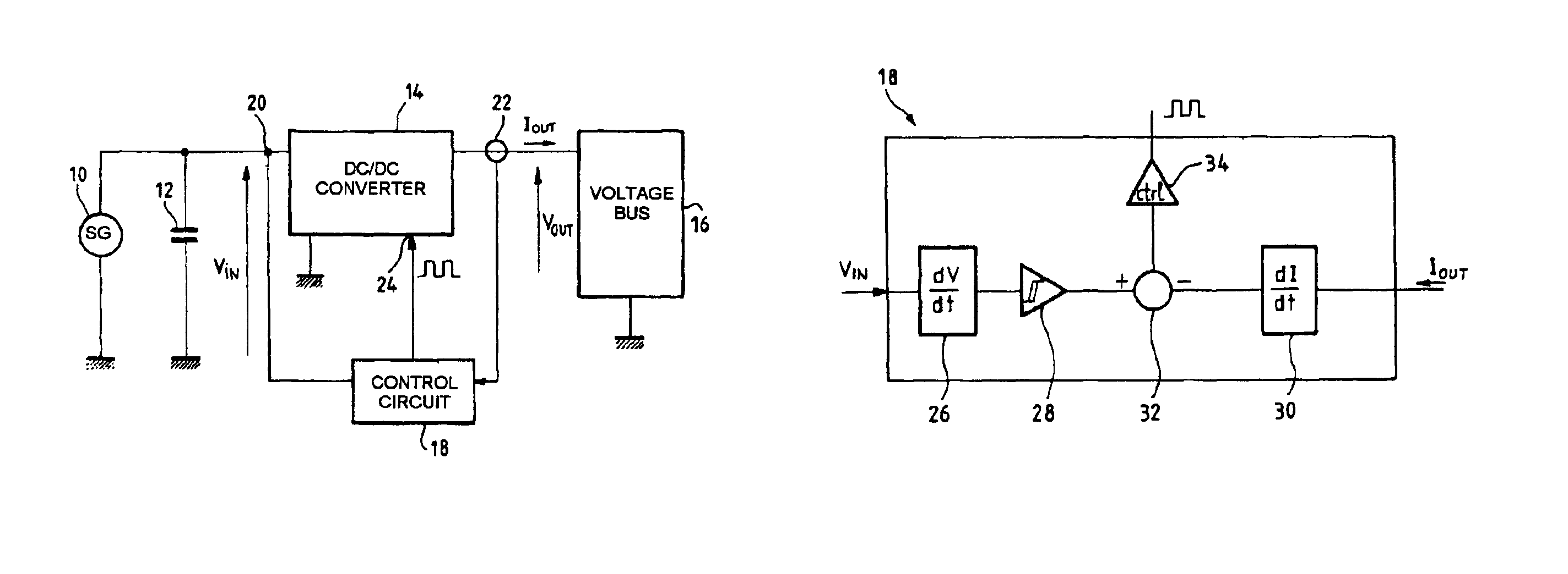
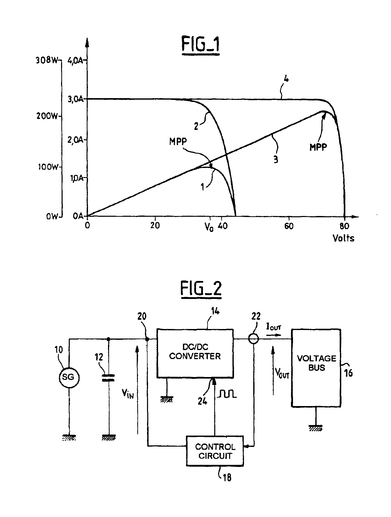
[0033]The remainder of the description gives one example of the application of the invention to maximum power point tracking in a solar generator. As explained above, this kind of generator is merely one example of a power supply whose graph of the power supplied as a function of the voltage at the terminals of the supply features a maximum.

[0034]FIG. 2 is a diagrammatic representation of one embodiment of a conditioned generator according to the invention, in an application of supplying power to a satellite voltage bus. The conditioned generator comprises a solar generator 10 and a conditioning circuit. The conditioning circuit enables the conditioned generator to deliver power at a fixed voltage, in other words to behave as a voltage supply, if the power delivered is less than the maximum power that the solar generator can supply, although the solar generator is able only to supply a variable power, up to the maximum power available, at varying voltages.

[0035]The figure shows the ...


PUM


Abstract

A circuit for conditioning a power supply whose graph of the power supplied as a function of the voltage at the terminals of the supply features a maximum comprises a DC / DC converter with an input to which power is supplied by the power supply and an output from which power is supplied to a load. A control circuit controls the converter in accordance with a power set point applied to the converter. The set point is a rising set point when the time derivative of the converter input voltage is higher than a negative first threshold value and a falling set point when the time derivative of the converter input voltage is lower than a positive second threshold voltage. The rate of variation of the average power when the set point is a rising set point is lower than the opposite of the rate of variation of the average power when the set point is a falling set point. The conditioning circuit enables the supply to deliver power at the maximum power point and is simple to implement.

Description

CROSS-REFERENCE TO RELATED APPLICATIONS[0001]This application is based on French Patent Application No. 02 10 140 filed Aug. 9, 2002, the disclosure of which is hereby incorporated by reference thereto in its entirety, and the priority of which is hereby claimed under 35 U.S.C. §119.BACKGROUND OF THE INVENTION[0002]1. Field of the Invention[0003]The present invention relates to power supplies and more precisely to the operation of power supplies which feature a maximum on the curve of the power supplied as a function of the voltage at the terminals of the supply.[0004]2. Description of the Prior Art[0005]For the above kind of supply, the power supplied is at a maximum when the voltage has a given value. For optimum operation of the power supply—to draw the maximum power therefrom—it is beneficial for the voltage at the terminals of the supply to be as closely equal to the aforementioned given value as possible.[0006]The solar generators used for satellites constitute one example of ...

Claims


Application Information

Patent Timeline
IPC IPC(8): G05F1/66G05F1/67H01L31/04
CPCG05F1/67Y10S323/906
Inventor DELEPAUT, CHRISTOPHE
Owner ALCATEL LUCENT SAS
Learn More