Catalytic converter

a technology of catalytic converters and mat supports, which is applied in the direction of machine/engine, physical/chemical process catalysts, separation processes, etc., can solve the problem that the substrate of the catalyst is too weak to resist the force of the mat supporting material necessary to prevent axial movemen

Inactive Publication Date: 2005-07-19
DELPHI TECH INC
View PDF20 Cites 23 Cited by
  • Summary
  • Abstract
  • Description
  • Claims
  • Application Information

AI Technical Summary

Benefits of technology

[0006]The drawbacks and disadvantages of the prior art are overcome by the catalytic converter of the exemplary embodiment of the present invention and its method of manufacture. A catalytic converter comprises a catalyst substrate comprising a catalyst and having one or more features on an outer surface. A shell, which includes an opening is concentrically disposed around the catalyst substrate. A mat support material is disposed between the catalyst substrate and shell, concentrically around the catalyst substrate. The feature of the catalyst substrate engages the mat support material to reduce the axial movement of the catalyst substrate. The catalyst substrate is concentrically disposed within the shell. The opening of the shell is secured using an end cone and / or an end plate.

Problems solved by technology

However, when using catalyst substrates that have frangible walls, for fast warm-up and low flow restriction, the catalyst substrate tends to be too weak to resist the mat support material forces necessary to prevent axial movement.

Method used


Image

  • Catalytic converter
  • Catalytic converter
  • Catalytic converter

Examples


Embodiment Construction

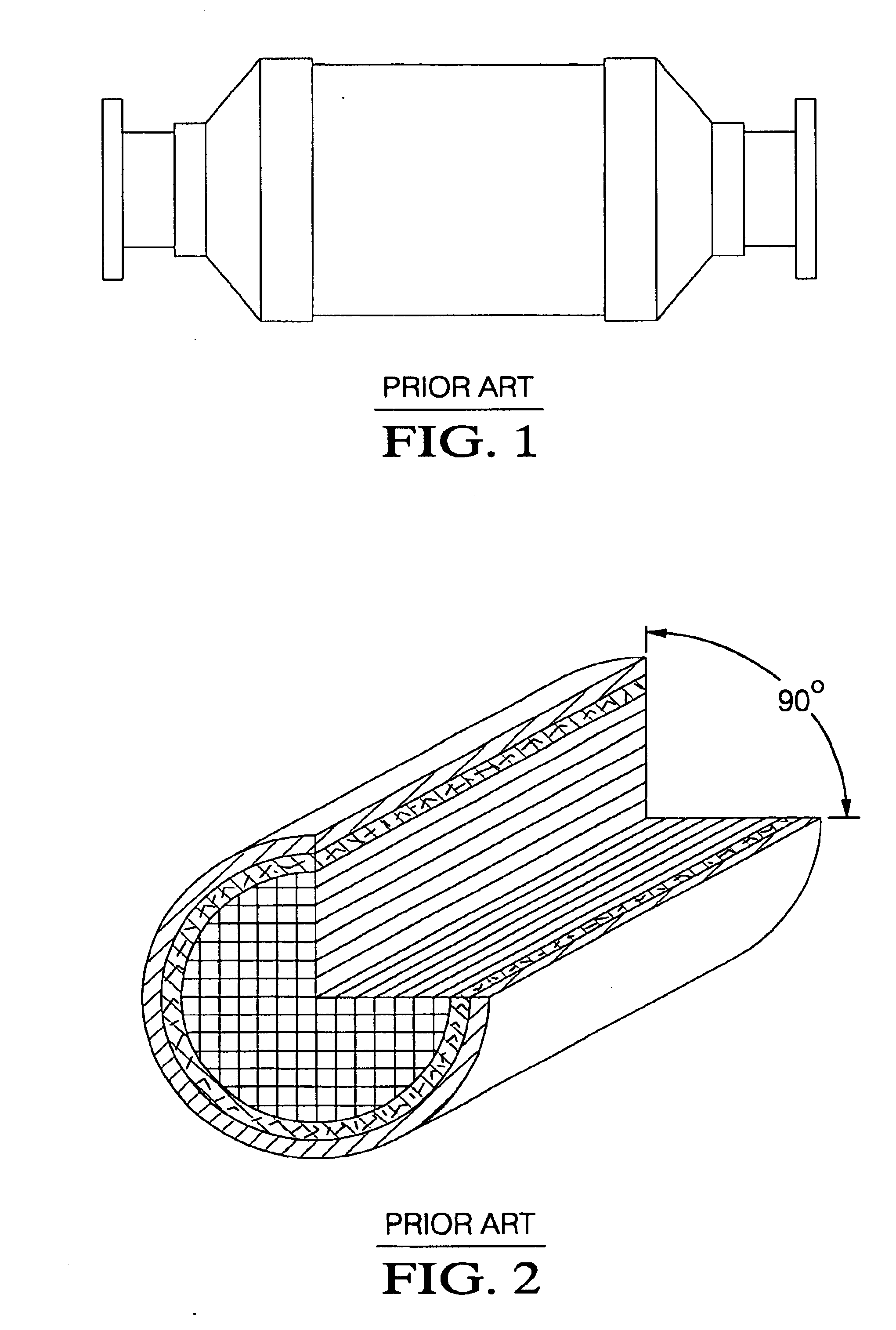
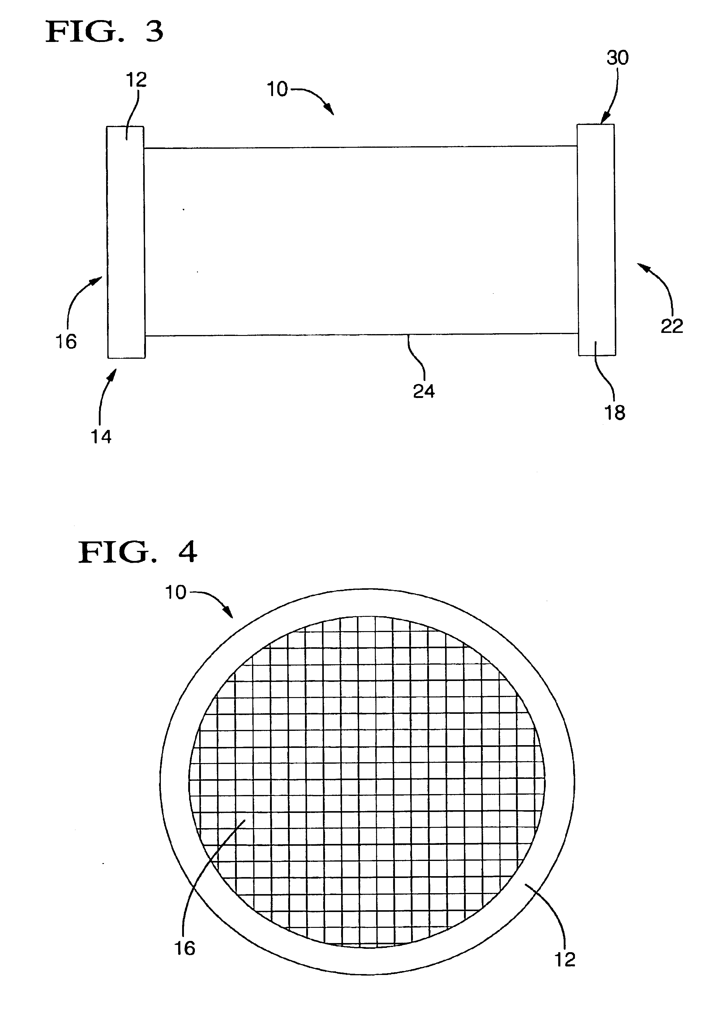
[0037]An internally insulated catalytic converter for use in a mobile vehicle comprises a catalyst substrate comprising a catalyst. The catalyst substrate can be concentrically disposed within a shell having an opening. A mat support material can be disposed concentrically between the catalyst substrate and the shell, around the catalyst substrate. An end cone, end plate, exhaust manifold, or the like, can secure the opening of the shell.

[0038]A non-internally insulated catalytic converter for use in a mobile vehicle comprises a catalyst substrate concentrically disposed within a shell. The shell can include an gas exhaust intake area, a gas exhaust outlet area, and a containment area disposed therebetween. The containment area can optionally be defined by a first shoulder concentrically disposed between the containment area and exhaust gas intake area, and by a second shoulder concentrically disposed between the containment area and the exhaust gas outlet area.

[0039]The catalyst su...


PUM

PropertyMeasurementUnit
temperaturesaaaaaaaaaa
heightaaaaaaaaaa
heightaaaaaaaaaa

Abstract

A catalytic converter comprises a catalyst substrate concentrically disposed in a shell and having a mat support material located concentrically in between the catalyst substrate and shell. The catalyst substrate includes structural features located on its outer surface that engage the mat support material. The shear forces exerted between the catalyst substrate and mat support material, in addition to the normally present frictional forces, reduce the axial movement of the catalyst substrate during assembly and operation of the catalytic converter.

Description

TECHNICAL FIELD[0001]The invention relates to catalytic converters for mobile vehicles and, more particularly, to an apparatus and method for reducing axial movement of a catalyst substrate in a catalytic converter.BACKGROUND OF THE INVENTION[0002]As is well known, the purification of exhaust gases from internal combustion engines, particularly in mobile vehicles, is generally achieved by a catalytic converter in which a ceramic or metallic element having a honeycomb cell structure, which is disposed in a gas-tight sheet metal shell, acts as a catalyst carrier. More precisely, this honeycomb cell structure or catalyst substrate is covered with a catalyst that contains a precious metal which functions, in the presence of a stoichiometric mixture of exhaust gases, to convert noxious or otherwise environmentally unfriendly components of the exhaust gas, such as hydrocarbons (HC), carbon monoxide (CO) and nitrogen oxides (NOx), to carbon dioxide (CO2), water (H2O) and nitrogen (N).[0003...

Claims


Application Information

Patent Timeline
Patent Type & Authority Patents(United States)
IPC IPC(8): B01J8/04B01J19/24F01N3/28
CPCB01J8/0438B01J19/2485F01N3/2853F01N3/2857B01J2208/00884F01N2330/02F01N2330/06
Inventor FOSTER, MICHAEL RALPHJANKOWSKI, PAUL E.
Owner DELPHI TECH INC
Why Eureka
Try Eureka