Shield electric cable connector

Inactive Publication Date: 2005-07-12
FURUKAWA ELECTRIC CO LTD
View PDF12 Cites 13 Cited by
  • Summary
  • Abstract
  • Description
  • Claims
  • Application Information

AI Technical Summary

Benefits of technology

[0007]An object of the present invention is to provide a shield electric cable connector that can be easily and automatically fixed to a shield electric cable by using machine and has excellent shield characteristics.

Problems solved by technology

When the shield electric cable connector disclosed in the publication is attached to a shield electric cable, however, an operator is required to do vexatious and complicated work of inserting the terminal portion of the shield electric cable into the sleeve and then caulking the sleeve.
Moreover, such work is unsuitable for automation utilizing machine, or mass production.
Thus, there is fear that there occurs a variation in shield characteristics.
If the sheath is deteriorated to shrink under the influence of heat, and the contact state between the sheath and the middle diameter portion of the sleeve becomes unstable, the sleeve cannot be firmly attached to the shield electric cable, resulting in a potential decline in the shield characteristics.

Method used


Image

  • Shield electric cable connector
  • Shield electric cable connector
  • Shield electric cable connector

Examples


Embodiment Construction

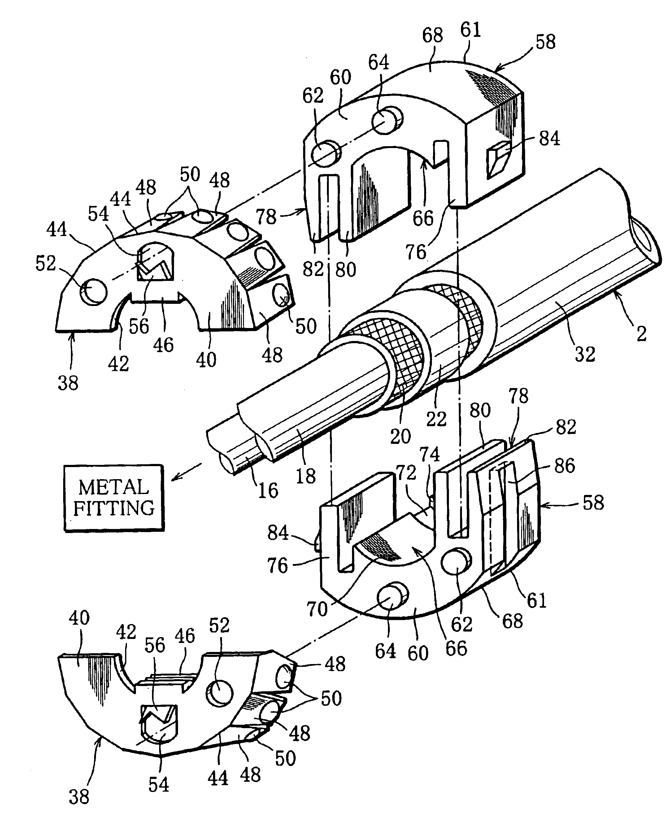
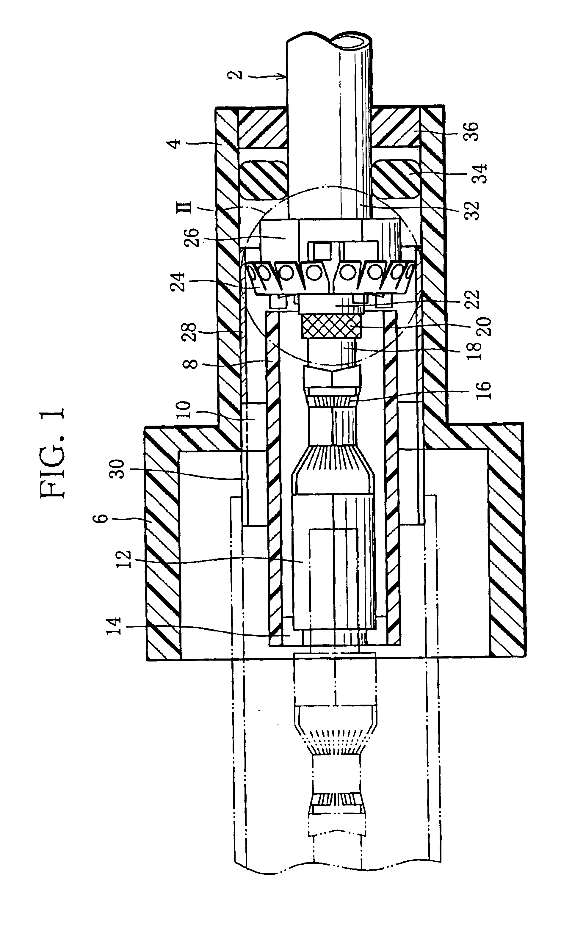
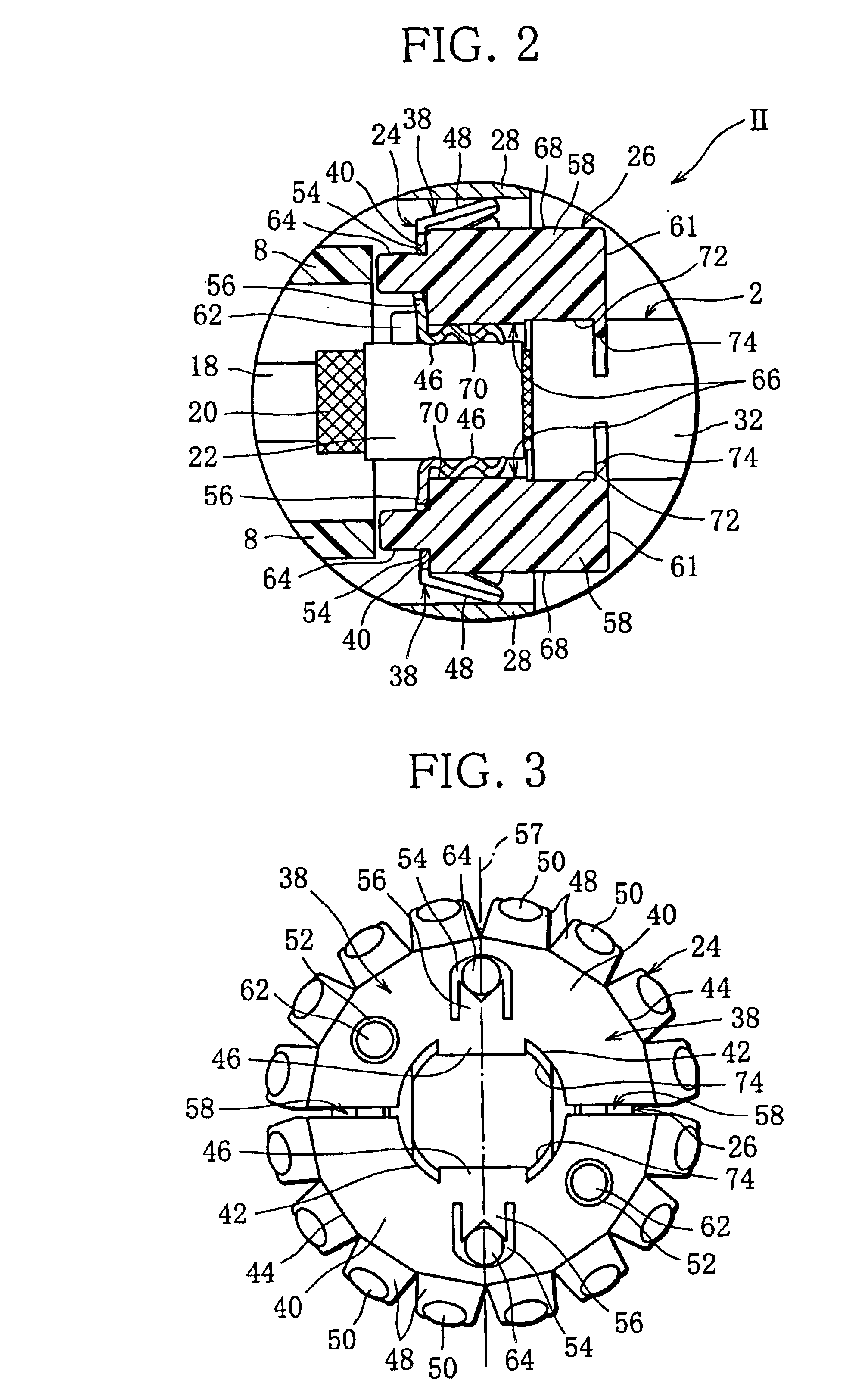
[0016]FIG. 1 illustrates a shield electric cable connector of an embodiment. The connector is fixed to a peeled terminal portion of a shield electric cable 2 and utilized for connecting the shield electric cable 2 to a mate member, such as another shield electric cable and a device.

[0017]The connector includes a cylindrical connector housing 4 having a tip end portion 6 with a large diameter. The tip end portion 6 is interfittable with a housing, not shown, of a connector that is attached to a shield electric cable of the mate member. Moreover, the housing 4 has a support portion 8 that is integrally formed in the inside on the tip end portion side. The support portion 8 is formed into a cylinder whose outer circumference is attached to the housing 4 through an arm 10.

[0018]Disposed in the support portion 8 is a female terminal (hereinafter referred to as metal fitting with reference number 12) having a tip end portion interfittable with a male terminal of the mate member. The metal...


PUM


Abstract

A shield electric cable connector for electrically connecting a shield electric cable to a mate member, wherein the shield electric cable includes one terminal portion that is peeled for connecting said connector and the mate member. The terminal portion has a conductive shield layer exposed from a sheath of the shield electric cable. The connector includes a conductive shield pipe surrounding the terminal portion of the shield electric cable and a conductive shield-connecting member surrounding the shield layer between the exposed shield layer and the shield pipe, the shield-connecting member electrically connecting the exposed shield layer to the shield pipe. The shield-connecting member has a pair of halves for sandwiching the exposed shield layer from both sides in a radial direction of the exposed shield layer.

Description

RELATED APPLICATIONS[0001]This application is a U.S. Continuation Application under 35 USC 111(a) of International Application PCT / JP03 / 01336, filed on 7 Feb. 2003.TECHNICAL FIELD[0002]The present invention relates to a shield electric cable connector for connecting a shield electric cable to a mate member.BACKGROUND ART[0003]A shield electric cable has a core wire for transmitting electric power and signals, that is covered with a shield layer with an insulating layer therebetween, thereby preventing the core wire from being a noise source at the electric power transmission or preventing an external noise from being superimposed on the core wire of the shield electric cable. In other words, the shield electric cable is secured of electromagnetic shield characteristics by the shield layer.[0004]In case that such a shield electric cable is connected to a mate member, such as another shield electric cable and a device, a shield electric cable connector is fixed to the peeled terminal ...

Claims


Application Information

Patent Timeline
IPC IPC(8): H01R9/05H01R13/658
CPCH01R9/0524H01R9/0527H01R13/65802H01R13/6581
Inventor KANEKO, SHUHEI
Owner FURUKAWA ELECTRIC CO LTD
Why Eureka
Try Eureka