
Apparatus for increasing brake cylinder pressure by controlling pump motor and reducing the pressure by controlling electric energy applied to control valve

Inactive Publication Date: 2005-07-05
TOYOTA JIDOSHA KK
View PDF38 Cites 64 Cited by
  • Summary
  • Abstract
  • Description
  • Claims
  • Application Information

AI Technical Summary

Benefits of technology

[0007]It is an object of the present invention to provide a novel hydraulic pressure control apparatus which is different from the hydraulic pressure control apparatus described above, namely, provide a hydraulic pressure control apparatus capable of controlling the fluid pressure in the brake cylinder, without controlling the electric energies to be applied to the pressure increase control valve and the pressure reduction control valve.

Problems solved by technology

This residual fluid pressure may cause a so-called “brake drag”, namely, some degree of braking even after the braking operation in question.
Accordingly, this normally open shut-off valve requires a comparatively large amount of consumption of the electric energy, and suffers from a relatively large operating noise, a relatively short life, and other problems.

Method used


Image

  • Apparatus for increasing brake cylinder pressure by controlling pump motor and reducing the pressure by controlling electric energy applied to control valve
  • Apparatus for increasing brake cylinder pressure by controlling pump motor and reducing the pressure by controlling electric energy applied to control valve
  • Apparatus for increasing brake cylinder pressure by controlling pump motor and reducing the pressure by controlling electric energy applied to control valve

Examples


second embodiment

[0218]The stationary vehicle braking control routine of FIG. 15 is formulated to increase the threshold EPS of the pressure difference ΔP used for selecting one of the pressure increase, hold and reduction modes, and to select the pressure hold mode in step S65 when the wheel speed is lower than the predetermined threshold even when the pressure difference ΔP is larger than the increased threshold EPS′. However, steps S65 and S67 may be eliminated so that the pressure increase mode is selected as long as the pressure difference ΔP is larger than the increased threshold EPS′. An increase in the threshold EPS results in increasing the chance of selecting the pressure hold mode. Further, the common pressure control in step S11 of FIG. 4 may be adapted to select the pressure hold mode when the change rate ΔPref of the target wheel brake cylinder pressure Pref is lower than a predetermined lower limit. In this case, a common pressure control routine illustrated in the flow chart of FIG. ...

third embodiment

[0224]While the above two embodiments are adapted to select one of the pressure increase mode, pressure hold mode and pressure reduction mode depending upon the pressure difference ΔP between the target wheel brake cylinder pressure Pref and the actual wheel brake cylinder pressure, the rate of change ΔPref of the target wheel brake cylinder as well as the pressure difference ΔP is taken into account to select one of the pressure increase, hold and reduction modes. An example of this arrangement according to the present invention is shown in FIG. 17.

[0225]In the third embodiment of FIG. 17, the pressure hold mode rather than the pressure increase mode is selected when the change rate ΔPref is not higher than a predetermined threshold EPS even while the pressure difference ΔP is larger than the predetermined threshold EPS. Further, the pressure hold mode rather than the pressure reduction mode is selected when the change rate ΔPref is not lower than the threshold EPS even while the p...

fourth embodiment

[0229]For instance, the control device 160 may be adapted to execute a motor control routine illustrated in the flow chart of FIG. 18 according to this invention. This motor control routine is executed as an interruption routine at a predetermined time interval. The routine is initiated with step S101 to determine whether a MOTOR START flag is set at “1”. If a negative decision (NO) is obtained in step S101, the control flow goes to step S102 to determine whether the low-pressure pump motor 40 has been commanded to be turned on (started). If an affirmative decision (YES) is obtained in step S102, the control f low goes to step S103 to set the MOTOR START flag to “1” and start a timer, and then to step S104 to apply the maximum voltage to the pump motor 40. Step S104 is followed by step S105 to determine whether a predetermined time has elapsed after starting of the timer, namely, after the maximum voltage has been applied to the pump motor 40. If a negative decision (NO) is obtained...


PUM


Abstract

Hydraulic pressure control apparatus for controlling a pressure of a brake cylinder pressure, including a pump device connected to the brake cylinder and including at least one set of a pump for delivering a pressurized fluid to the brake cylinder and a pump operating electric motor, a low-pressure source for storing the fluid discharged from the brake cylinder, a solenoid-operated pressure control valve disposed between the low-pressure source and the brake cylinder and operated with an electric energy applied thereto, for controlling the brake cylinder pressure depending upon the electric energy, and a controller including a pressure increase control device for increasing the brake cylinder pressure by controlling the electric motor, and a pressure reduction control device or reducing the brake cylinder pressure by controlling the electric energy applied to the control valve.

Description

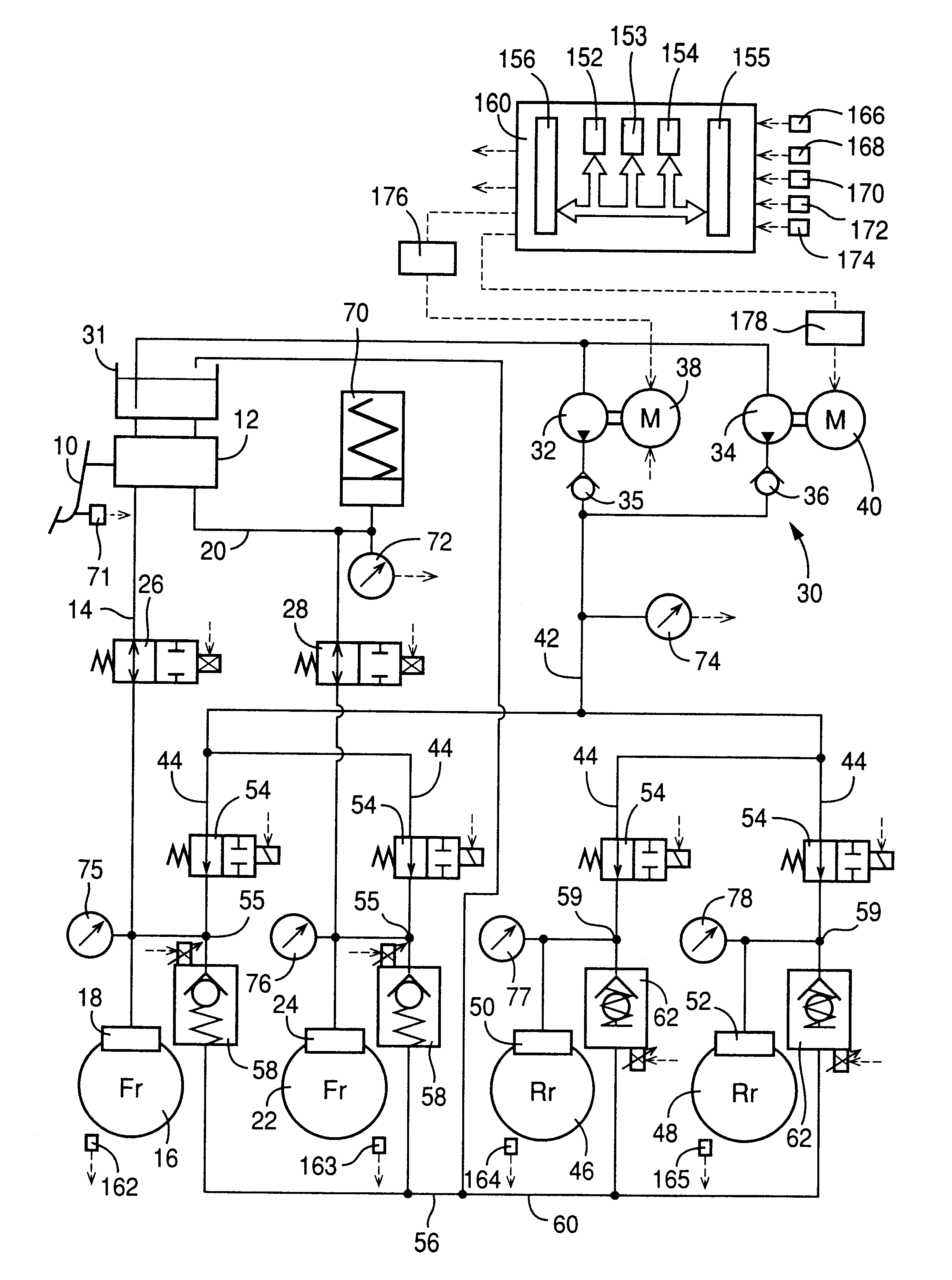
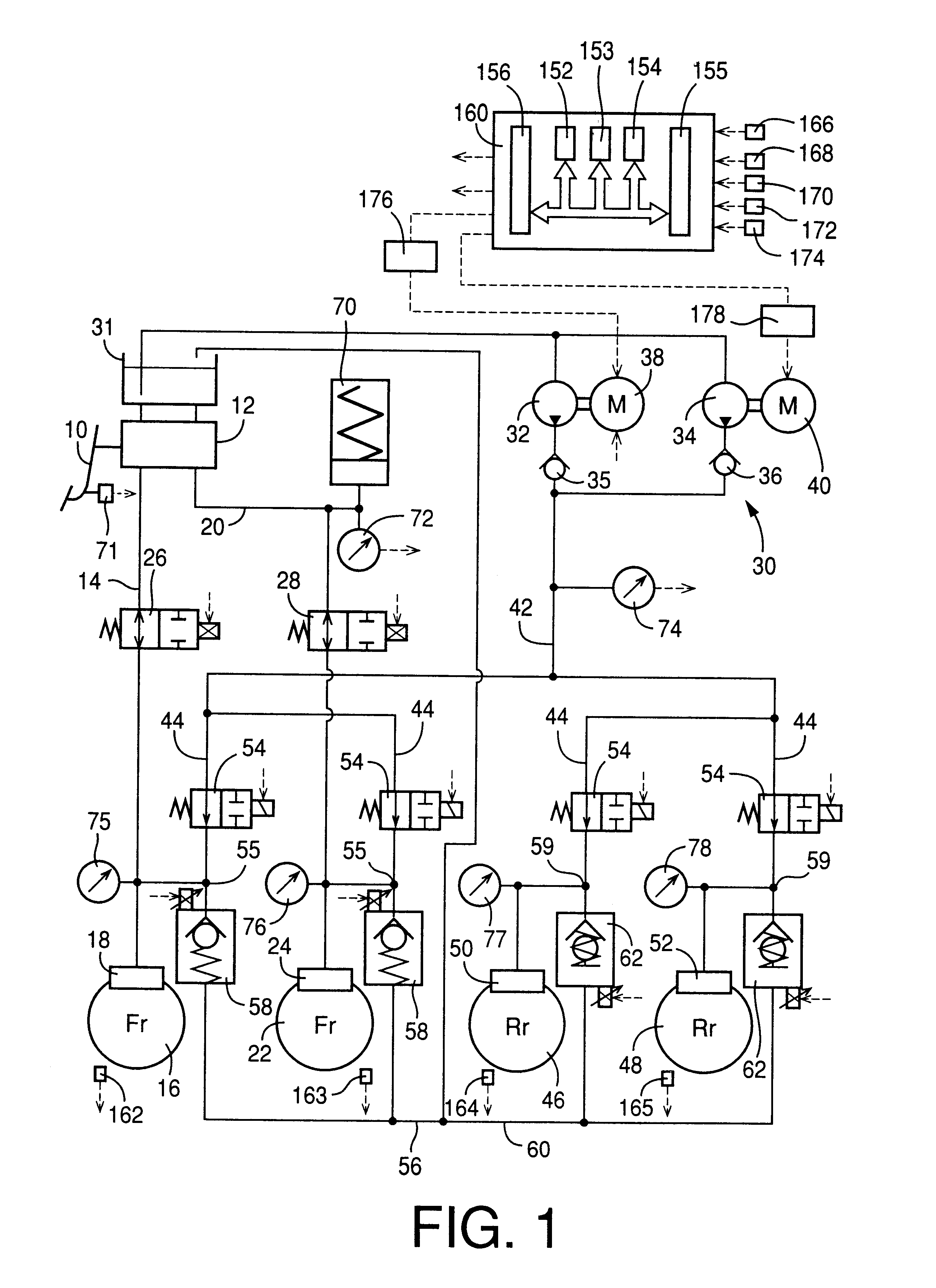
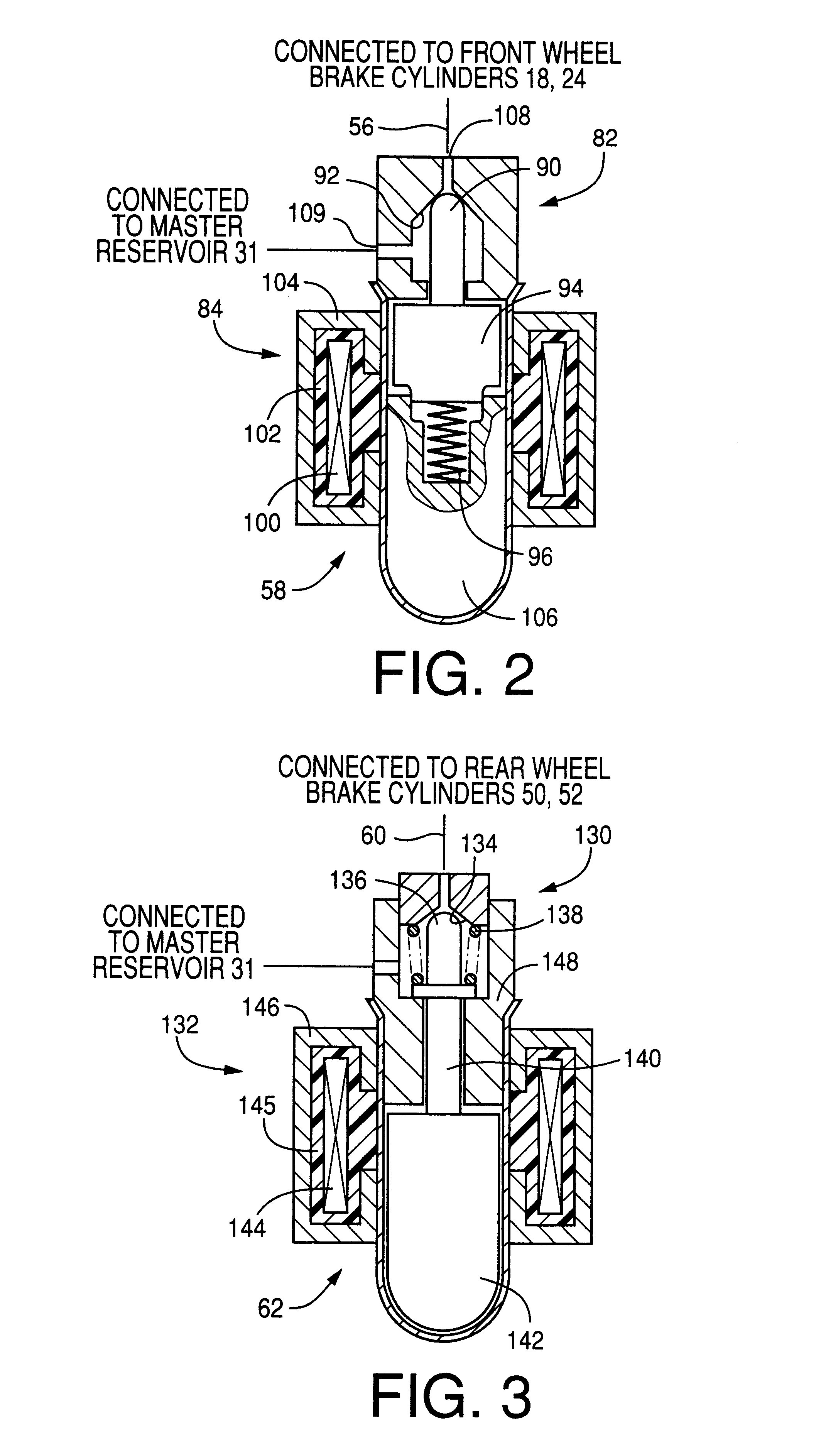
BACKGROUND OF THE INVENTION[0001]1. Field of the Invention[0002]The present invention relates to a hydraulic pressure control apparatus for controlling a fluid pressure in a hydraulically operated brake cylinder.[0003]2. Discussion of the Related Art[0004]JP-A-10-322803 (published on Dec. 4, 1998, before the present invention was made) discloses such a hydraulic pressure control apparatus using an electrically operated hydraulic pressure source as a high-pressure source. This hydraulic pressure control apparatus includes (1) the above-indicated high-pressure source which includes a pump, an elcctrc motor or operating the pump, and an accumulator for storing a working fluid pressurized by the pump, for supplying the pressurized fluid to a brake cylinder, (2) a low-pressure source for storing the fluid discharged from the brake cylinder, (3) a solenoid-operated pressure increase control valve disposed between the high-pressure source and the brake cylinder, and electrically controlled...

Claims


Application Information

Patent Timeline
IPC IPC(8): B60T7/12B60T8/40B60T8/34B60T8/48B60T8/24B60T8/32B60T8/50B60T8/36
CPCB60T7/122B60T8/24B60T8/3275B60T8/36B60T8/367B60T8/405B60T8/4059B60T8/4063B60T8/4081B60T8/4827B60T8/5093
Inventor OHKUBO, MASAYASUNAKAMURA, KIYOHARUSAKAI, AKIRASOEJIMA, SHINICHISHIMURA, AMANE
Owner TOYOTA JIDOSHA KK
Learn More