Mechanical pipe coupling derived from a standard fitting

Inactive Publication Date: 2005-07-05
VICTAULIC
View PDF57 Cites 61 Cited by
  • Summary
  • Abstract
  • Description
  • Claims
  • Application Information

AI Technical Summary

Benefits of technology

[0017]A second expanded region is positioned adjacent to the first expanded region, the second expanded region preferably having a larger diameter than the first expanded region and sized to receive a retainer positionable therein for retaining the pipe end within the pipe coupling, and a support washer positioned adjacent to the retainer. The support washer has a radially inwardly facing surface having a diameter substantially equal to and coaxial with the socket diameter for circumferentially engaging and supporting the pipe end. The two-point support provided by the socket and the support washer provides substantial resistance to bending of the pipe within the coupling. The support washer preferably has a circumferential collar which engages and supports the retainer. The second expanded region forms an open end of the pipe coupling for receiving the pipe end. A lip is positioned at the open end and extends substantially radially inwardly to be engageable with the support washer when it is positioned in the second expanded region. The shoulder and the lip capture the sealing member, the retainer, and the support washer between one another.
[0018]Preferably, the retainer adapted to interfit within the opening of the pipe coupling comprises a ring sized to circumferentially engage the second expanded region and a plurality of flexible, resilient, elongated teeth arranged circumferentially around the ring. The teeth project substantially radially inwardly from the ring and are angularly oriented in a direction away from the opening. The teeth are engageable circumferentially with the pipe end for preventing movement of the pipe end outwardly from the bore.
[0021]It is still another object of the invention to provide a standard mechanical pipe coupling which can be used in a “size-on-size” association with an appropriate standard pipe for increased economy, improved fluid flow and compactness.
[0022]It is again another object of the invention to provide a standard mechanical pipe coupling which has substantial resistance to bending preventing excessive free play between pipe and coupling.

Problems solved by technology

Next, the cleaned surfaces are coated with a flux material, usually an acid flux, which further disrupts the oxide layer (especially when heated) and permits metal to metal contact between the fitting, the pipe end and the solder.
Many steps are required to make the soldered joint, thus, it is a time consuming and labor intensive operation.
Furthermore, the solder often contains lead, and the flux, when heated, can give off noxious fumes, thus, exposing the worker to hazardous substances which can adversely affect health over time.
The joint is typically heated with an open gas flame which can pose a fire hazard.
While these mechanical couplings avoid the above identified problems associated with soldered joints, they can suffer from one or more of the following disadvantages.
This is more expensive than adapting the standard fitting appropriate to the standard pipe in what is known as a “size-on-size” fitting.
Furthermore, the retainer may not provide adequate pull-out strength, and the pipe end could be inadvertently separated from the coupling, for example, during a pressure spike within the pipe, caused by a sudden closing of a valve (the “water hammer effect”) which places the joint under tension.
The retainer also does not help keep the pipe end coaxial with the coupling upon insertion, allowing the pipe end to tip and deform the retainer and gouge the inside surface of the coupling or an elastomeric seal, such as an O-ring.
Mechanical joints with retainers also tend to have little resistance to bending, allowing the pipe too much angular free play and permitting the pipe to “walk” out of the joint under repeated reversed bending loads.
Excessive free play also tends to disengage the teeth on one side of the retainer and deform the teeth on the other side, weakening the joint.
Furthermore, use of an enlarged section to accommodate the retainer may cause energy loss impeding fluid flow if the fluid is forced to flow into a coupling having a larger cross-sectional area.
In general, when mechanical couplings are designed to overcome the aforementioned inherent disadvantages, they tend to suffer from a high part count, making them relatively complex and expensive.

Method used


Image

  • Mechanical pipe coupling derived from a standard fitting
  • Mechanical pipe coupling derived from a standard fitting
  • Mechanical pipe coupling derived from a standard fitting

Examples


Embodiment Construction

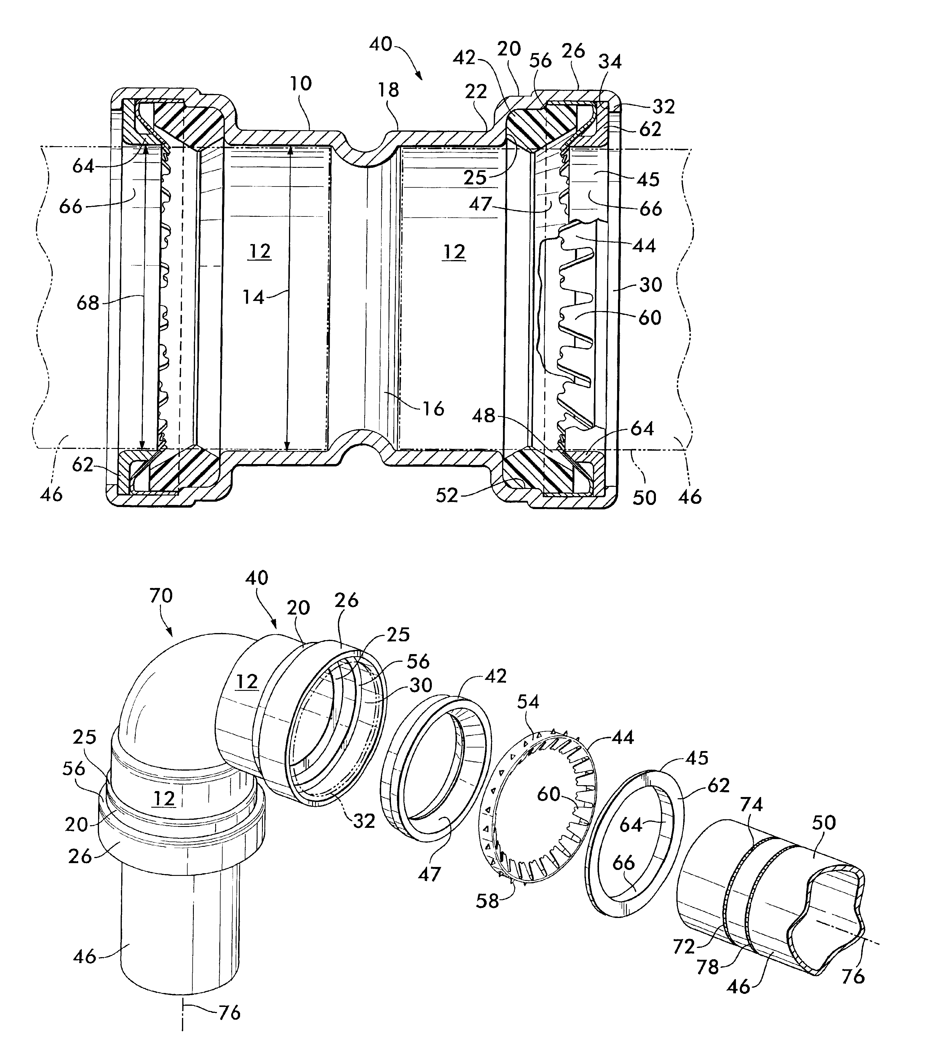
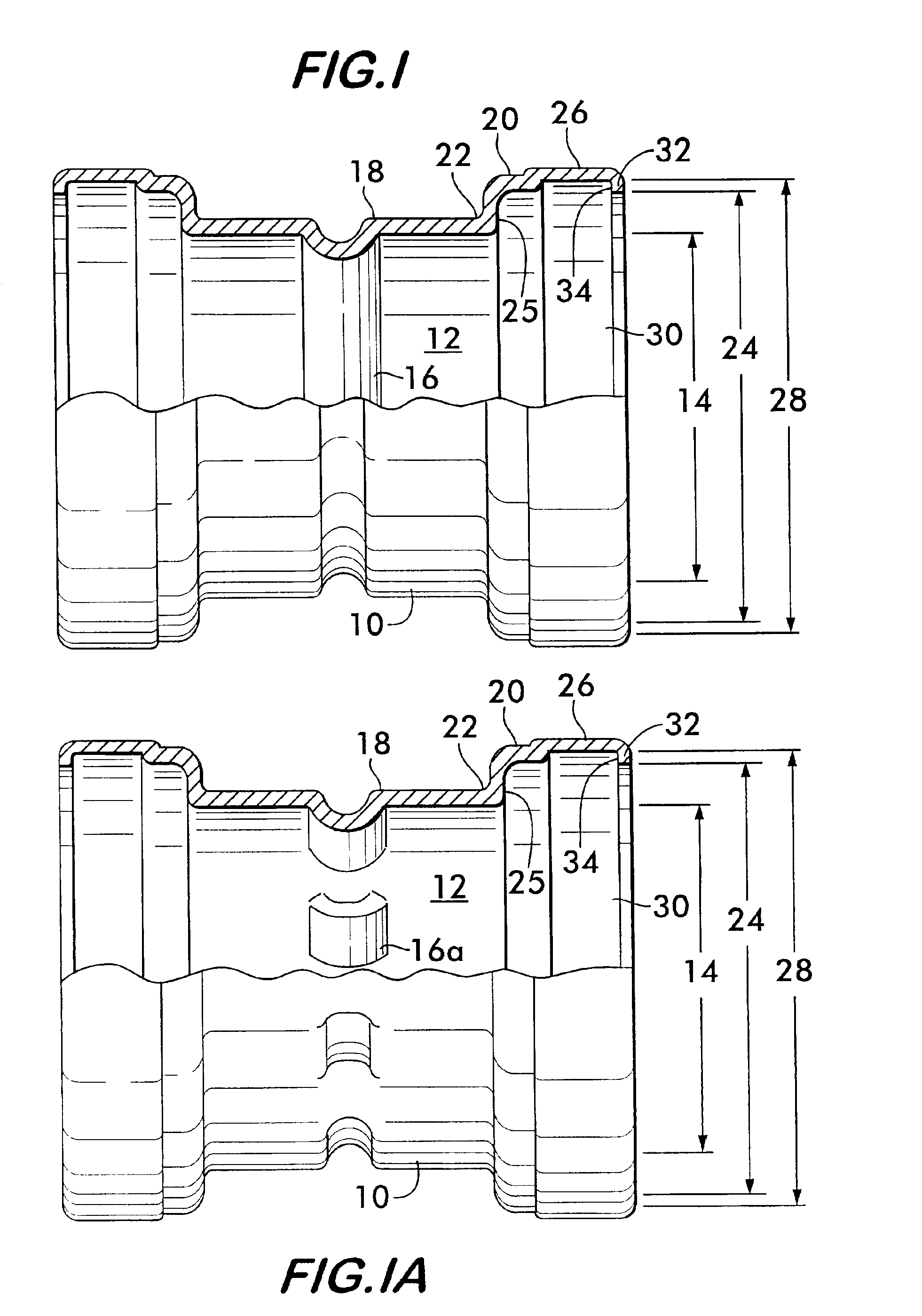
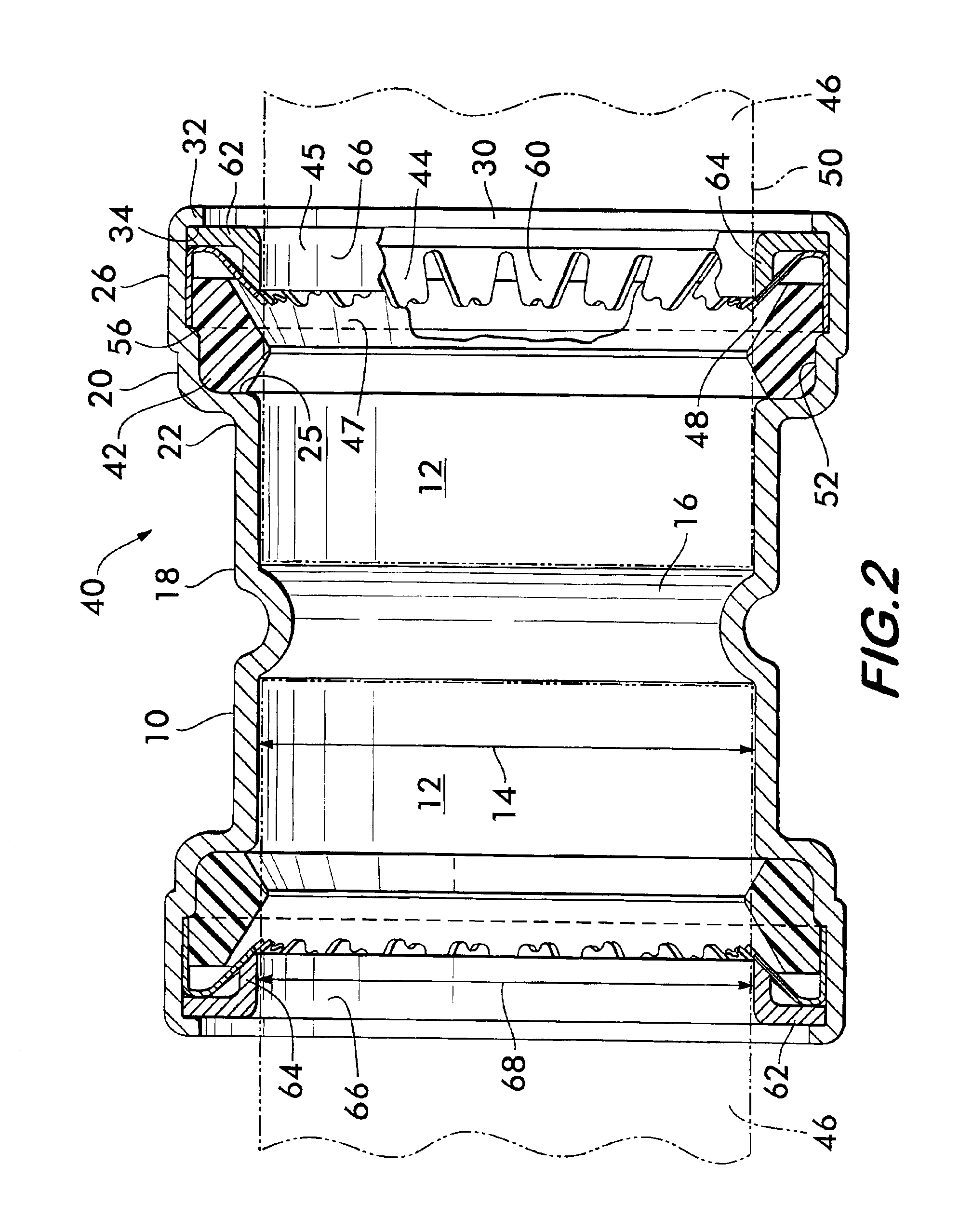
[0032]FIG. 1 shows a pipe coupling housing 10 according to the invention having a socket 12 with an inner diameter 14 sized according to a standard to receive a pipe end sized, according to a compatible standard, to interfit within the socket 12. Preferably, coupling housing 10 is a modification of an existing standard pipe fitting, for example, an ASME Standard pipe fitting according to Standard number B16.22a-1998 for wrought copper and copper alloy solder joint pressure fittings. Fittings meeting the specification of other standards, such as the German DIN standard and the British BS standard, may also be modified to derive the coupling housing 10.

[0033]A stop surface 16 is positioned adjacent to one end 18 of the socket 12. Stop surface 16 extends radially inwardly and is, thus, engageable with an end of a pipe received within the socket to prevent the pipe end from passing through the coupling housing. Stop surface 16 is circumferentially continuous around housing 10, but may a...


PUM


Abstract

A coupling for joining pipe segments together is disclosed. The coupling is derived from a standard fitting and has a housing with a socket and a first expanded region adjacent to the socket and a second expanded region adjacent to the first expanded region. A sealing member is positioned in the first expanded region, a retainer is positioned in the second expanded region and a support washer having transversely oriented radial and coaxial flanges is positioned adjacent to the retainer. A lip turned inwardly on the second expanded region overlaps the radial flange and captures the support washer, retainer and sealing member within the coupling. The retainer has a plurality of radial teeth angularly oriented to engage a pipe and prevent its removal from the coupling.

Description

RELATED APPLICATION[0001]This application is a continuation-in-part of U.S. application Ser. No. 10 / 007,951, filed Dec. 3, 2001, which is based on and claims priority of U.S. Provisional Application No. 60 / 262,820, filed Jan. 19, 2001.FIELD OF THE INVENTION[0002]This invention relates to couplings for pipes and especially to mechanical couplings derived from standard fittings which effect a strong, reliable joint with a fluid-tight seal without the need for brazing or soldering.BACKGROUND OF THE INVENTION[0003]The construction of piping networks requires couplings that can form fluid-tight joints between pipe ends which can withstand external mechanical forces, as well as internal fluid pressure and reliably maintain the integrity of the joint. Many forms of joints are known, such as brazed or soldered joints, threaded joints, welded joints and joints effected by mechanical means.[0004]For example, copper tubing, which is used extensively throughout the world to provide water servic...

Claims


Application Information

Patent Timeline
IPC IPC(8): F16L37/00F16L37/091A61M39/00F16L37/08F16L21/08
CPCF16L37/091F16L19/061F16L19/086F16L21/02
Inventor SNYDER, SR., RONALD R.WILK, JR., CHARLES E.THAU, JR., LAWRENCE W.DOLE, DOUGLAS R.CAROM, TERRANCE M.
Owner VICTAULIC
Why Eureka
Try Eureka