
Record condition extraction system and method of dielectric recording medium, and information recording apparatus

a recording condition and extraction system technology, applied in the field of recording condition extraction system and extraction method of dielectric recording medium, and information recording apparatus, can solve the problems of difficult to obtain a detection signal having enough s/n ratios to the microdomain on the order of nm, and hardly any concrete condition extraction method of forming with good reproducibility, etc., to achieve high density and stable microdomain

Inactive Publication Date: 2005-06-28
YASUO CHO +1
View PDF5 Cites 38 Cited by
  • Summary
  • Abstract
  • Description
  • Claims
  • Application Information

AI Technical Summary

Benefits of technology

[0008]It is therefore an object of the present invention to provide a record condition extraction system and a record condition extraction method of the dielectric recording medium, as well as an information recording apparatus, in order to form a high-density and stable microdomain in the electric material.

Problems solved by technology

However, only resolution on the order of μm can be expected in this method, and it requires time because of the need to pass through processes of the chemical etching and the like until the actual observation.
In this method, however, it is difficult to obtain a detection signal having enough S / N ratios to the microdomain on the order of nm.
However, there is hardly any concrete condition extraction method of forming with good reproducibility a micro polarization domain that has a stable level for recording and reproducing.

Method used


Image

  • Record condition extraction system and method of dielectric recording medium, and information recording apparatus
  • Record condition extraction system and method of dielectric recording medium, and information recording apparatus
  • Record condition extraction system and method of dielectric recording medium, and information recording apparatus

Examples


first embodiment

(I) First Embodiment

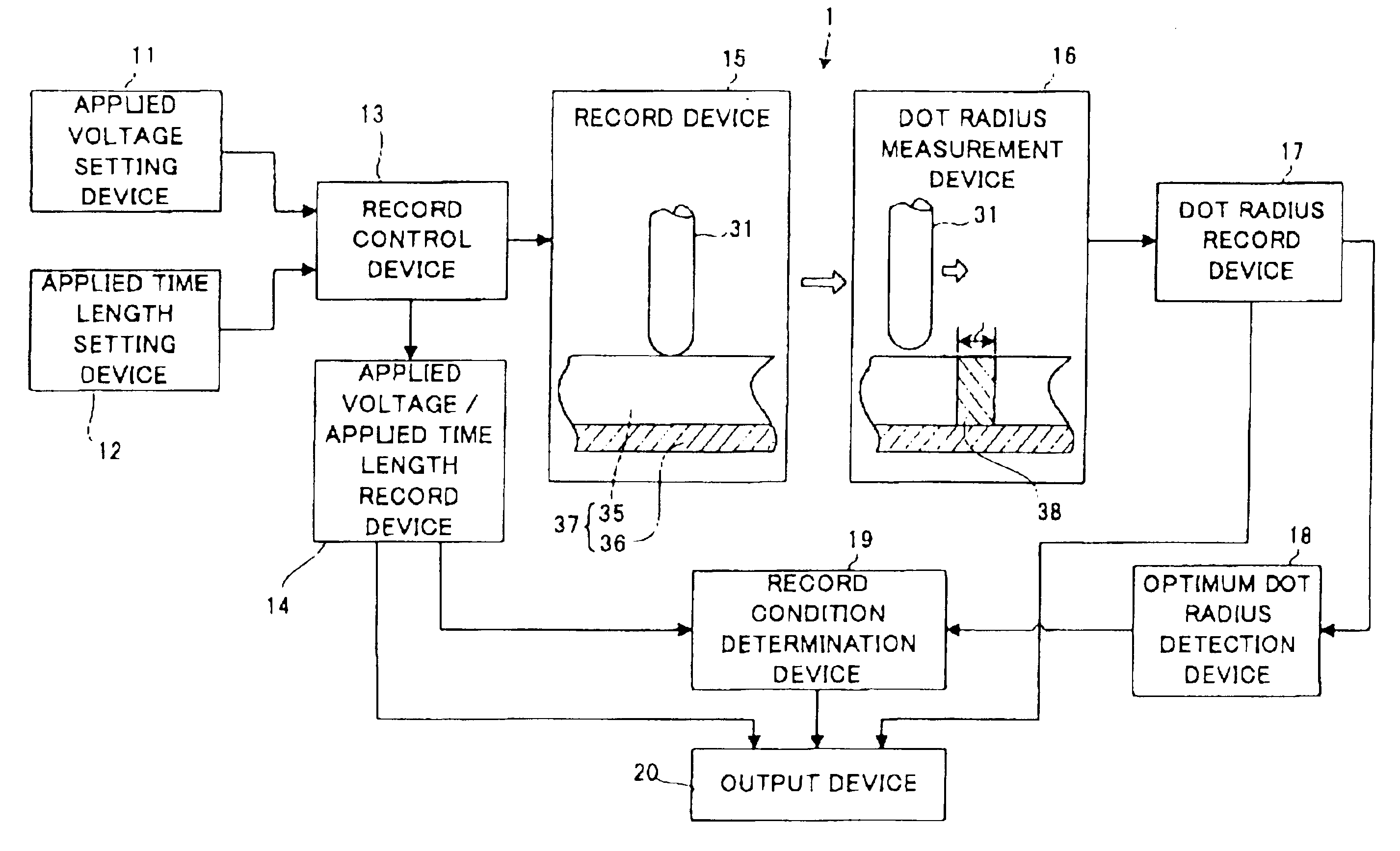
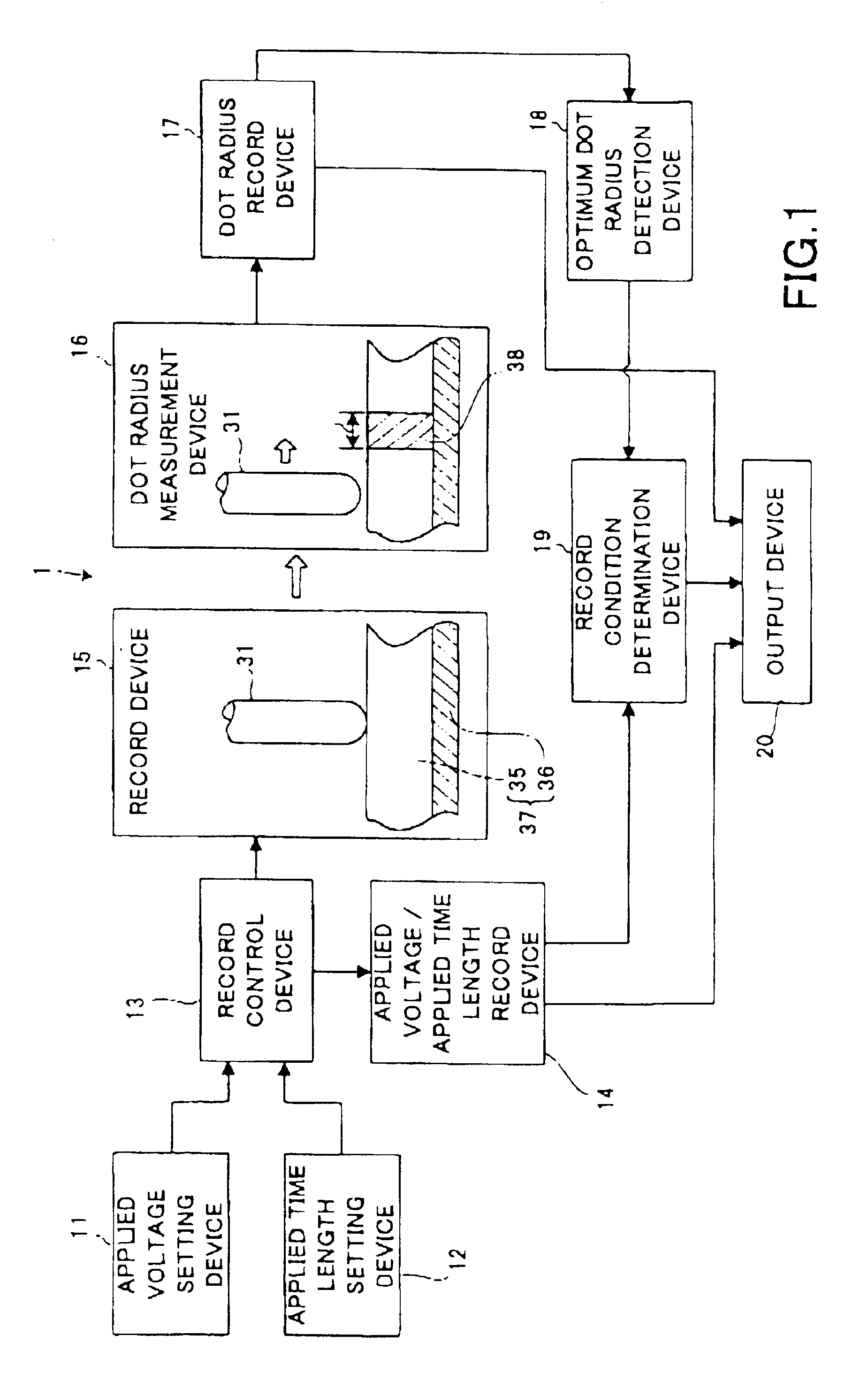
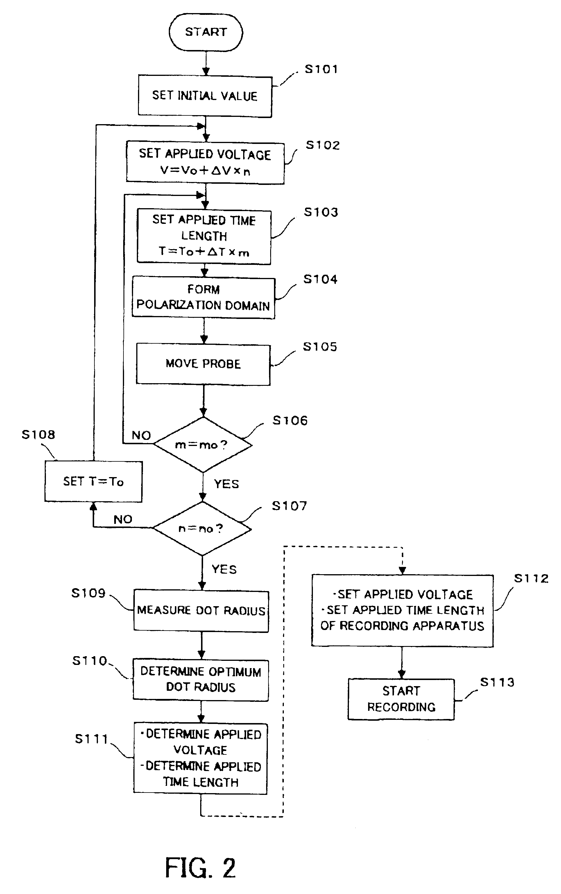
[0076]The record condition extraction system and method of the dielectric recording medium of the present invention will be explained with reference to FIG. 1 to FIG. 7. FIG. 1 is a block diagram showing a structure of a record condition extraction system for obtaining a record condition of a dielectric recording medium. FIG. 2 is a flow chart showing operational flow of the record condition extraction system. FIG. 3A to FIG. 3D are schematic diagrams showing record conditions to the dielectric recording medium, FIG. 3A showing the condition that a polarization domain is formed on the end of a probe, FIG. 3B showing the condition that the polarization domain further grows, FIG. 3C showing the condition that the polarization domain reaches the back surface of the recording medium and the polarization domain is completely formed, and FIG. 3D showing a strength distribution of an electric field in the recording medium by the probe. FIG. 4 to FIG. 6 are measurement d...

second embodiment

(II) Second Embodiment

[0111]Next, an allowable range of the dot radius on the basis of the smallest and stable polarization domain and the voltage applied time length will be explained with FIG. 8 and FIG. 9. This is useful to determine the size of the polarization domain which is more stable and to obtain degree of freedom for setting the applied time length while keeping the limitation of the recording speed or the recording density Incidentally, FIG. 8 is a diagram showing the relationship between the dot radius and the voltage applied time length when certain allowable values are set with respect to the optimum dot radius shown in FIG. 5, for example. FIG. 9 is a flowchart showing the operational flow of the record condition extraction system shown in FIG. 2 when the allowable values are set with respect to the optimum dot radius.

[0112]As shown in FIG. 8, on the dot radius of the polarization domain, allowable range Δr1 in the plus direction and allowable range Δr2 in the minus ...

third embodiment

(III) Third Embodiment

[0114]Next, the information recording apparatus provided with setting devices for setting the applied voltage and the applied time length extracted the record condition extraction system of the dielectric recording medium of the present invention will be explained.

[0115]As shown in FIG. 10, an information recording apparatus 3 is provided with: the dielectric recording medium 37 equipped with the dielectric substance 35 and the electrode 36; the probe 31; an electrode 51; an AC (Alternating Current) signal generator 52; a recording signal generator 53; an applied voltage setting device 11; an applied time length setting device 12; an adder 54; an oscillator 55; a FM (Frequency Modulation) demodulator 56; a signal detection device 57; an inductor L; an inductor La; and a capacitance Ca. Obviously, it is provided with other various general functions as the information recording apparatus; however, their explanation is omitted.

[0116]The dielectric recording medium...


PUM


Abstract

The record condition extraction system (1) of a dielectric recording medium is intended to obtain an applied voltage and an applied time length to be recorded when recording information in the dielectric recording medium. The record condition extraction system (1) is provided with: an applied voltage setting device (11); an applied time length setting device (12); a record control device (13); an applied voltage / applied time length record device (14); a record device (15); a dot radius measurement device (16); a dot radius record device (17); an optimum dot radius detection device (18); a record condition determination device (19); and an output device (20). The applied voltage setting device (11) and the applied time length setting device (12) set a voltage and a time applied to a probe (31) of the record device (15), respectively. The dot radius of a polarization domain 38, which is recorded at the record device (15), is measured at the dot radius measurement device (16), and the optimum polarization domain (38) is obtained at the optimum dot radius detection device (18). The applied voltage and the applied time length which have formed the polarization domain (38) are extracted as an optimum record condition.

Description

BACKGROUND OF THE INVENTION[0001]1. Field of the Invention[0002]The present invention relates to a record condition extraction system for and a record condition extraction method of obtaining an optimum record condition of a dielectric recording medium which records information in a microdomain of a dielectric substance with high density, as well as an information recording apparatus.[0003]2. Description of the Related Art[0004]Recently, many types of dielectric materials and piezoelectric materials have been developed, and most of them are used for ultrasonic elements, optical elements, a memory, and the like. In accordance with the fact, a method of measuring a remanent polarization distribution of the dielectric material and local anisotropy of the piezoelectric material has been developed. Also, by using this technique, another technique of recording information in the dielectric material and reproducing the information has been developed.[0005]Conventionally, in order to observ...

Claims


Application Information

Patent Timeline
IPC IPC(8): G11B9/02G11B9/00G11B11/00G11B11/08G01Q60/24G01Q60/46G01Q80/00G01Q90/00G11B9/14
CPCB82Y10/00G11B9/02G11B9/1472G11B9/14G11B11/08G11B11/007
Inventor CHO, YASUOONOE, ATSUSHI
Owner YASUO CHO
Learn More