
High performance probe system

a probe system and high-performance technology, applied in the direction of individual semiconductor device testing, semiconductor/solid-state device testing/measurement, instruments, etc., can solve the problems of tensile distortion and attenuation of signals

Inactive Publication Date: 2005-06-28
FORMFACTOR INC
View PDF28 Cites 131 Cited by
  • Summary
  • Abstract
  • Description
  • Claims
  • Application Information

AI Technical Summary

Benefits of technology

The solution enables the reliable transmission of high-frequency signals up to approximately 100 GHz with improved bandwidth and reduced signal distortion by minimizing transmission line junctions and maintaining consistent impedance across the signal path.

Problems solved by technology

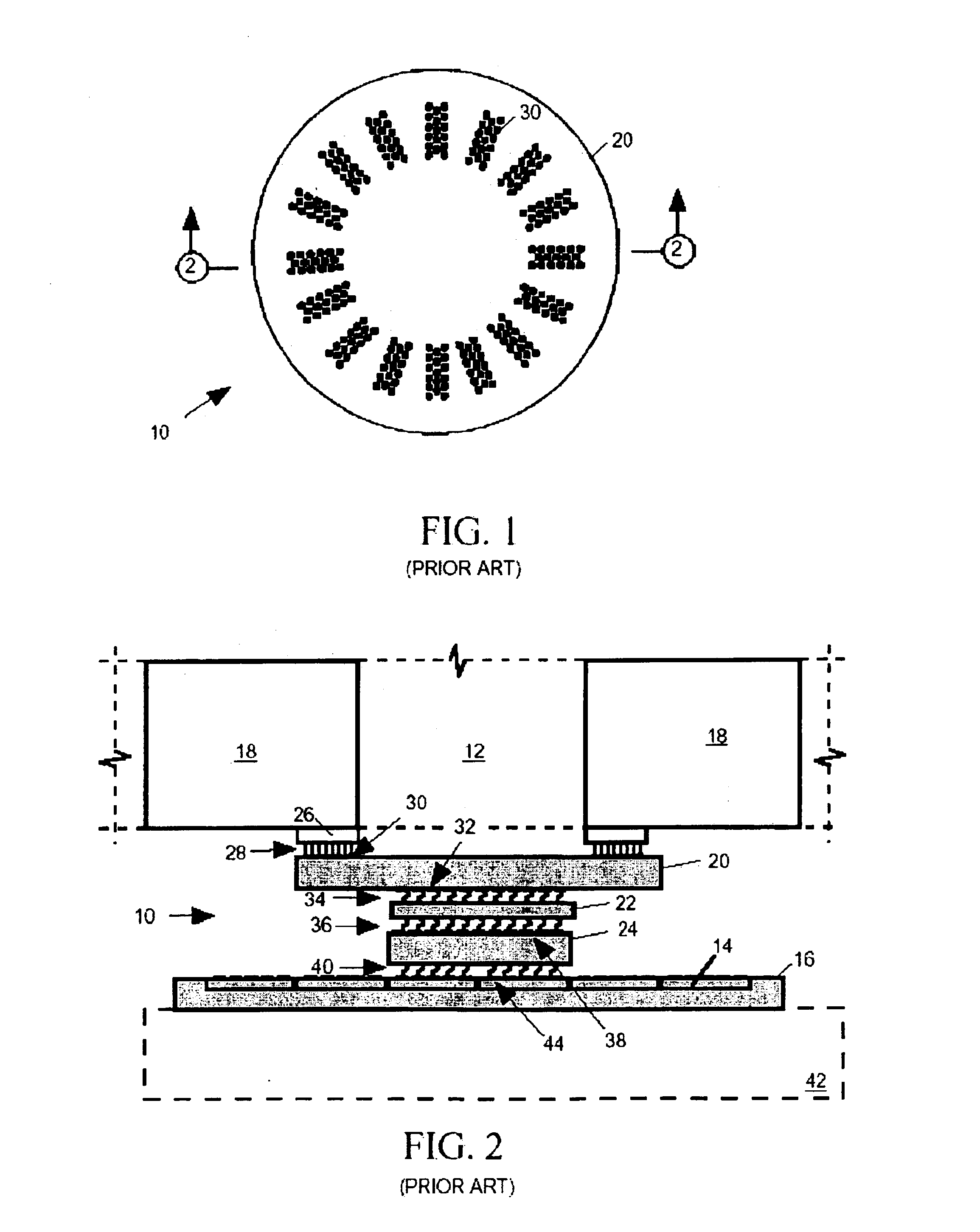
One problem probe board assembly 10 shares to some degree with any interconnect system, is that the signal paths it provides tend to distort and attenuate signals, particularly signals having high frequency components.

Method used


Image

  • High performance probe system
  • High performance probe system
  • High performance probe system

Examples


Embodiment Construction

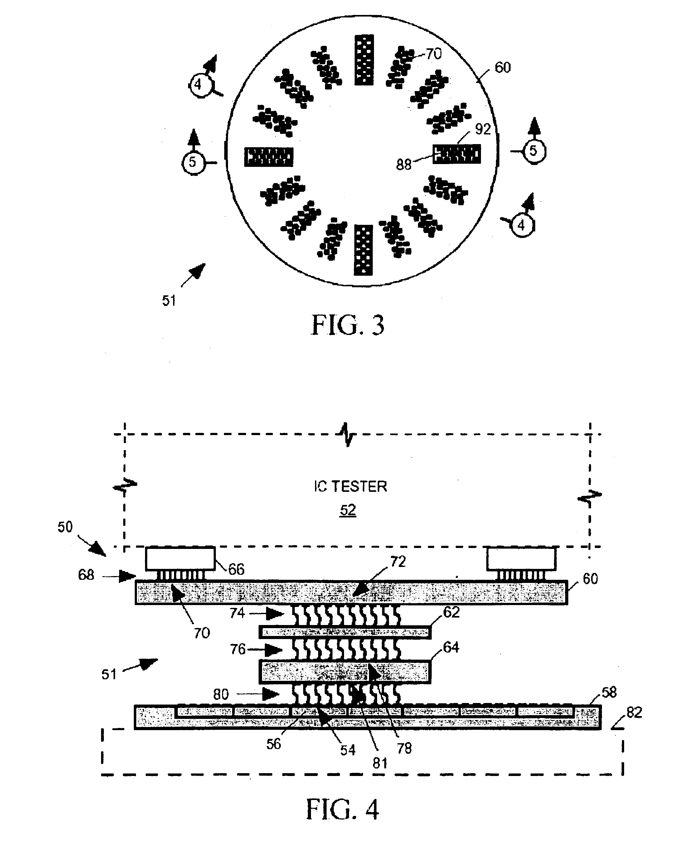
[0047]The present invention is directed to a probe board assembly for providing signal paths between an integrated circuit (IC) tester and input / output (I / O), power and ground pads of one or more ICs to be tested either while the ICs are still in the form of die on a semiconductor wafer or after they have been separated from one another. The specification describes exemplary embodiments and applications of the invention considered by the applicant(s) to be the best modes of practicing the invention. It is not intended, however, that the invention be limited to the exemplary embodiments described below or to the particular manner in which the embodiments operate.

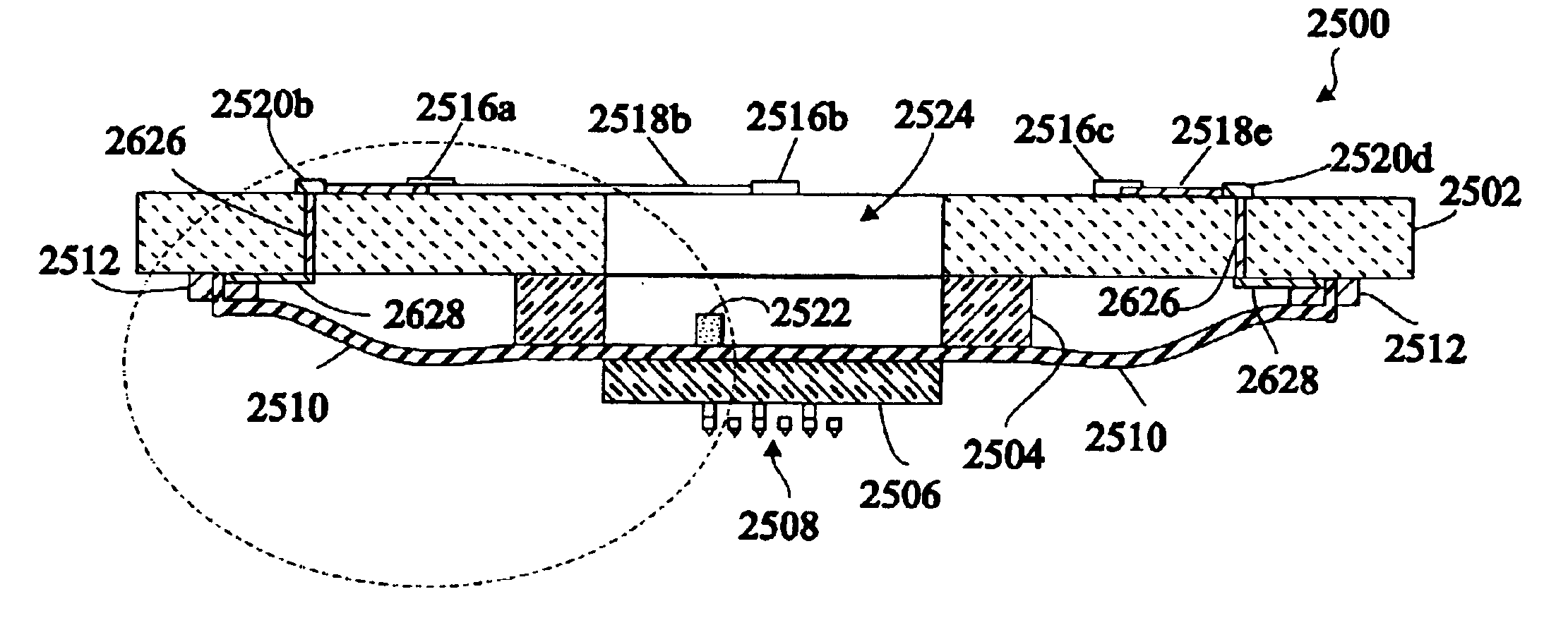
[0048]FIG. 3 is a plan view and FIGS. 4 and 5 are sectional elevation views of a probe system 50 in accordance with an exemplary embodiment of the invention for providing signal paths between an IC tester 52 to I / O, power and ground pads 54 on the surfaces of ICs 56, for example, while still in the form of die on a semiconduc...


PUM


Abstract

A probe system for providing signal paths between an integrated circuit (IC) tester and input / output, power and ground pads on the surfaces of ICs to be tested includes a probe board assembly, a flex cable and a set of probes arranged to contact the IC's I / O pads. The probe board assembly includes one or more rigid substrate layers with traces and vias formed on or within the substrate layers providing relatively low bandwidth signal paths linking the tester to probes accessing some of the IC's pads. The flex cable provides relatively high bandwidth signal paths linking the tester to probes accessing others of the IC's pads. A flex strip may alternatively be disposed behind a substrate with probes.

Description

CROSS-REFERENCE TO RELATED APPLICATION[0001]This application is a continuation-in-part of pending U.S. patent application Ser. No. 10 / 142,548, filed May 8, 2002.BACKGROUND OF THE INVENTION[0002]1. Field of the Invention[0003]The invention relates to a system for providing paths suitable for high frequency signals passing between an integrated circuit (IC) test equipment and pads on the surfaces of ICs to be tested.[0004]2. Description of Related Art[0005]Integrated circuits (ICs) are often tested while still in the form of die on a semiconductor wafer. The following U.S. patents describe exemplary probe board assemblies for providing signal paths between an integrated circuit tester and input / output (I / O), power and ground pads on the surfaces of ICs formed on a semiconductor wafer: U.S. Pat. No. 5,974,662 issued Nov. 2, 1999 to Eldridge et al, U.S. Pat. No. 6,064,213 issued May 16, 2000 to Khandros, et al and U.S. Pat. No. 6,218,910 issued Apr. 17, 2001 to Miller.[0006]FIG. 1 is a ...

Claims


Application Information

Patent Timeline
Patent Type & Authority Patents(United States)
IPC IPC(8): G01R1/073G01R31/26G01R3/00H01L21/66
CPCG01R1/07314G01R3/00H01L22/00
Inventor CHRAFT, MATTHEWHENSON, ROY J.MILLER, CHARLES A.TSENG, CHIH-CHIANG
Owner FORMFACTOR INC
Learn More