
Automatic gain control device for a burst-mode optical receiver

a burst-mode optical receiver and automatic gain control technology, applied in gain control, instruments, electromagnetic transceivers, etc., can solve the problems of difficult for the controller to correctly determine the actual voltage-level information, and cost to replace existing copper-based subscriber lines with optical subscriber lines

Inactive Publication Date: 2005-06-28
SAMSUNG ELECTRONICS CO LTD
View PDF10 Cites 18 Cited by
  • Summary
  • Abstract
  • Description
  • Claims
  • Application Information

AI Technical Summary

Benefits of technology

The present invention provides an optical receiver with a burst-mode function that can automatically adjust the gain control for detecting signals. This allows for faster response times and reduces the time needed for the AGC loop to stabilize. The receiver includes a pre-amplifier and a bottom-level detector for analyzing the bottom level of the signal and outputting a signal denoting the presence of a signal and a reset signal for initialization at intervals between packets. An automatic-gain-control signal is generated based on the presence of a signal and includes a first transistor and a second transistor connected to a capacitor for charging or discharging a voltage. The drain voltage of the second transistor becomes low when the capacitor is charged but becomes high when the capacitor is discharged.

Problems solved by technology

However, it is costly to replace existing copper-based subscriber lines with optical subscriber lines, such as FTTH.
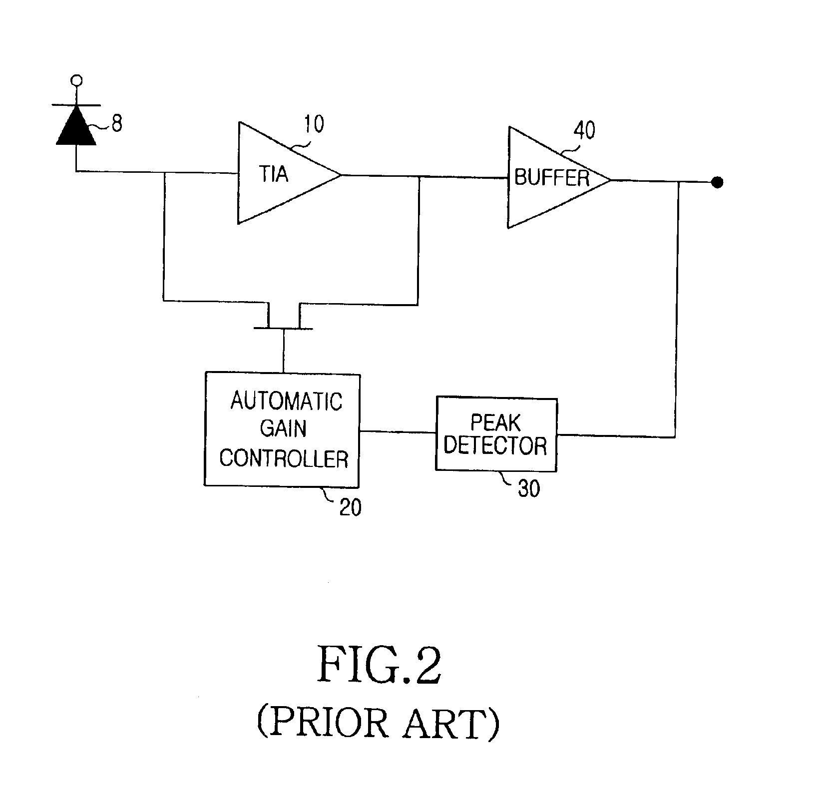
However, this automatic gain controller has a problem in determining the presence of a low-level signal because it is difficult for the controller to correctly determine the actual voltage-level information only through detecting the peak value of a low-level signal.

Method used


Image

  • Automatic gain control device for a burst-mode optical receiver
  • Automatic gain control device for a burst-mode optical receiver
  • Automatic gain control device for a burst-mode optical receiver

Examples


Embodiment Construction

[0027]Hereinafter, a preferred embodiment of the present invention will be described with reference to the accompanying drawings. For the purposes of clarity and simplicity, a detailed description of known functions and configurations incorporated herein will be omitted as it may make the subject matter of the present invention unclear.

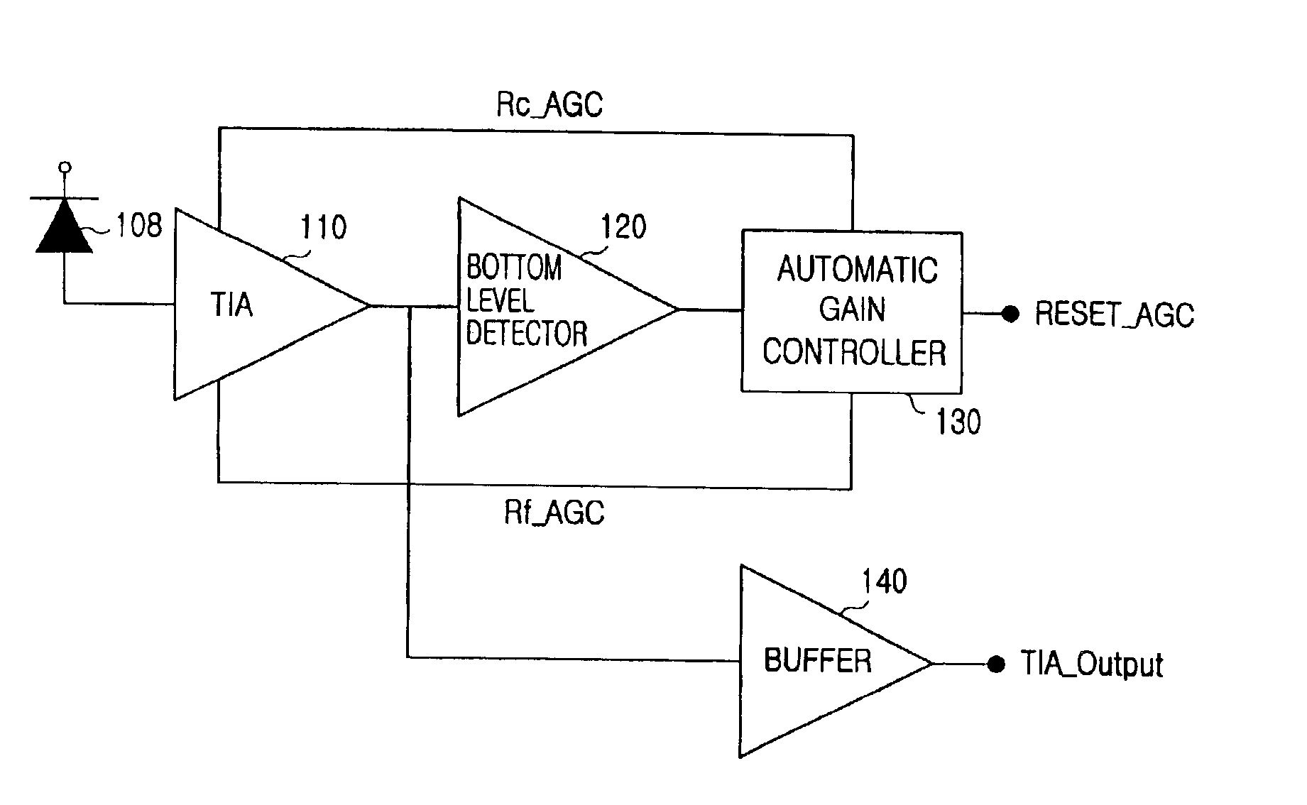
[0028]FIG. 3 shows the construction of a burst-mode optical receiver according to the embodiment of the present invention. As shown, the burst-mode optical receiver comprises an optical detector 108, a trans-impedance amplifier (TIA) 110, a bottom signal-level detector 120, an automatic gain controller 130, and a buffer 140.

[0029]In operation, the TIA 110 converts a current signal outputted from the optical detector 108 to a corresponding voltage signal, then provides the voltage signal to the bottom level detector 120. The bottom level detector 120 detects the bottom level of the signal output from the TIA 110 and informs the presence of a signal and...


PUM


Abstract

An automatic-gain-control device in an optical receiver is provided and includes a pre-amplifier for converting a current signal outputted from an optical detector to a voltage signal and a bottom level detector for detecting the bottom level from the output of the pre-amplifier, the automatic-gain-control device comprising a bottom signal-level-determining section for analyzing the bottom level from the bottom level detector and outputting a signal denoting the presence of a signal and a reset signal for initialization at intervals between packets; and an automatic-gain-control signal generating section for providing an automatic-gain-control signal by showing the presence of a signal, the automatic-gain-control-signal-generating section including a first transistor which turns on according to a signal from the bottom signal-level-determining section and a second transistor which is connected to a capacitor for charging or discharging a voltage applied by the first transistor, and the drain voltage of which becomes low when the capacitor is charged but becomes high when the capacitor is discharged.

Description

CLAIM OF PRIORITY[0001]This application claims priority to an application entitled “Automated Gain Control Device For a Burst-Mode Optical Receiver,” field in the Korean Intellectual Property Office on Apr. 26, 2002 and assigned Serial No. 2002-23065, the contents of which are hereby incorporated by reference.BACKGROUND OF THE INVENTION[0002]1. Field of the Invention[0003]The present invention relates to a burst-mode optical receiver and more particularly to a burst-mode optical receiver that can determine an input signal and generate on its own a reset signal for initialization during intervals between the packets.[0004]2. Description of the Related Art[0005]The next generation of communication services require FTTH (Fiber-To-The Home), which installs optical fiber directly into subscribers' homes in order to provide more information to the subscribers at a higher speed. However, it is costly to replace existing copper-based subscriber lines with optical subscriber lines, such as F...

Claims


Application Information

Patent Timeline
Patent Type & Authority Patents(United States)
IPC IPC(8): H03G3/30H03F3/08H03G3/20H04B10/07H04B10/2507H04B10/272H04B10/293H04B10/40H04B10/50H04B10/524H04B10/54H04B10/564H04B10/572H04B10/58H04B10/60H04B10/69
CPCH03G3/3084H04B10/60
Inventor DOH, HEE-CHANPARK, GIL-YONGWON, SHIN-HEEOH, YUN-JEPARK, TAE-SUNGKI, HYEON-CHEOL
Owner SAMSUNG ELECTRONICS CO LTD
Learn More