MRI visible catheter balloon

Inactive Publication Date: 2005-06-28
ABBOTT CARDIOVASCULAR
View PDF36 Cites 20 Cited by
  • Summary
  • Abstract
  • Description
  • Claims
  • Application Information

AI Technical Summary

Benefits of technology

[0011]In a presently preferred embodiment, the MRI visible medical device or component thereof is configured to be expandable or inflatable. It is particularly important to avoid disadvantageous effects on the strength of expandable or inflatable members, such as catheter balloons and vascular grafts, because the members are required to not tear or burst during expansion thereof. Thus, the relatively low loading of ferromagnetic or paramagnetic material, in accordance with the invention, is particularly advantageous in expandable or inflatable members.

Problems solved by technology

However, in a presently preferred embodiment, there is an insufficient amount of the ferromagnetic or paramagnetic material in or on the balloon wall to make the balloon radiopaque.
Specifically, such prior art catheter balloons would require a relatively large amount of radiopaque material to make the balloon radiopaque, which would consequently reduce the strength and effect the compliance of the balloon.

Method used


Image

  • MRI visible catheter balloon
  • MRI visible catheter balloon
  • MRI visible catheter balloon

Examples


Embodiment Construction

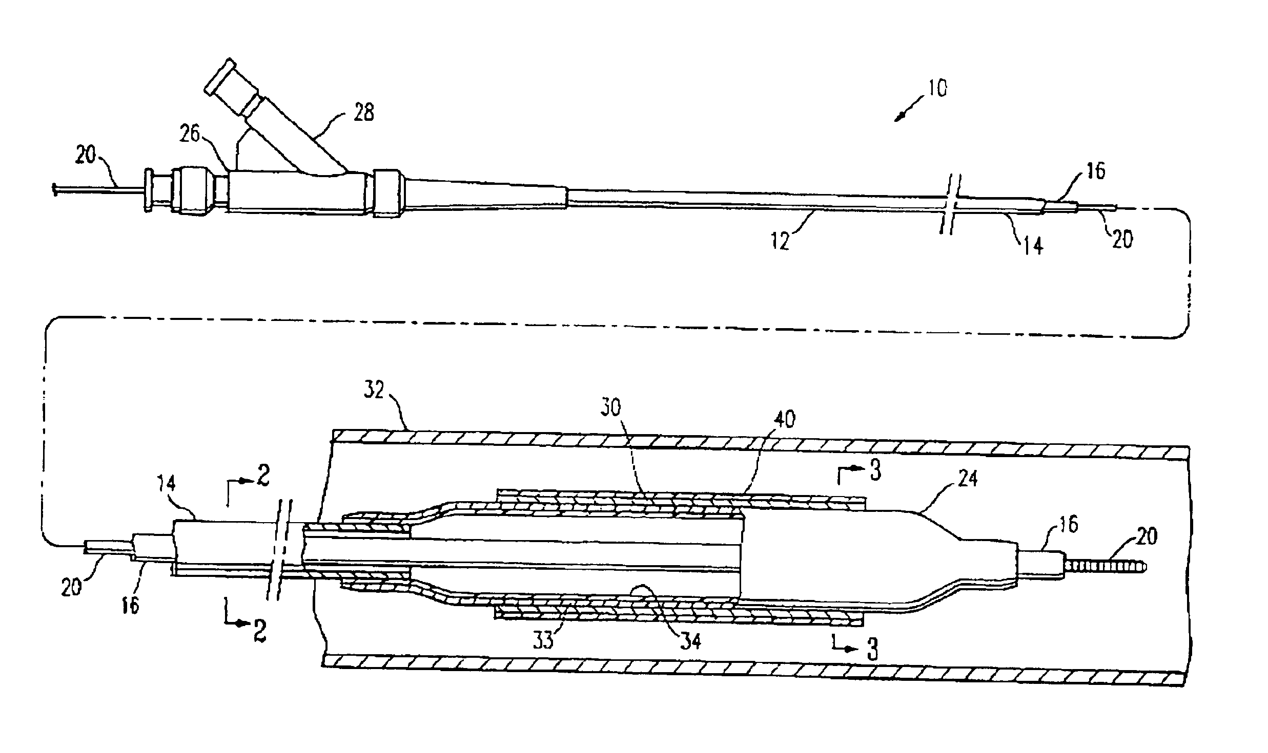
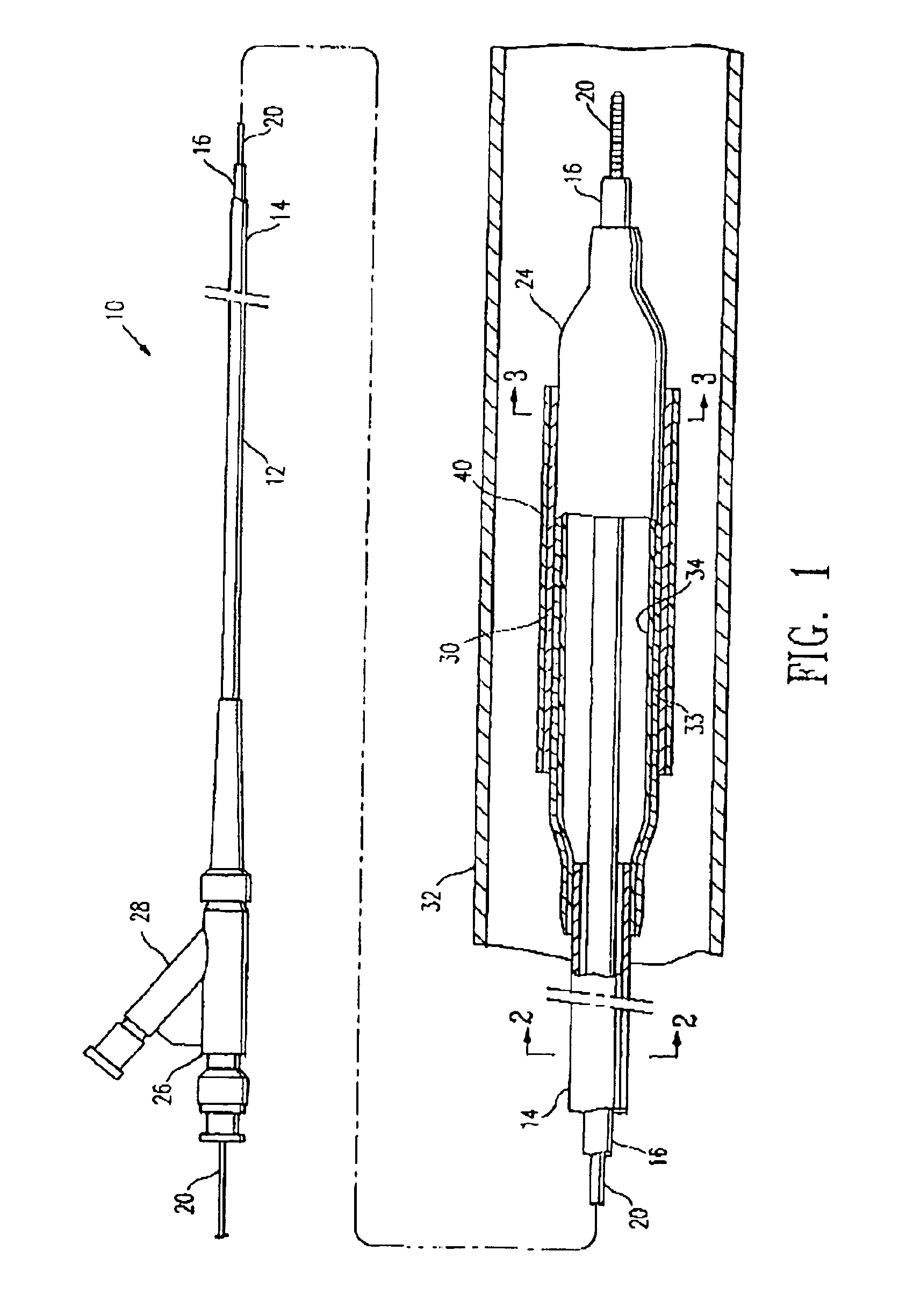
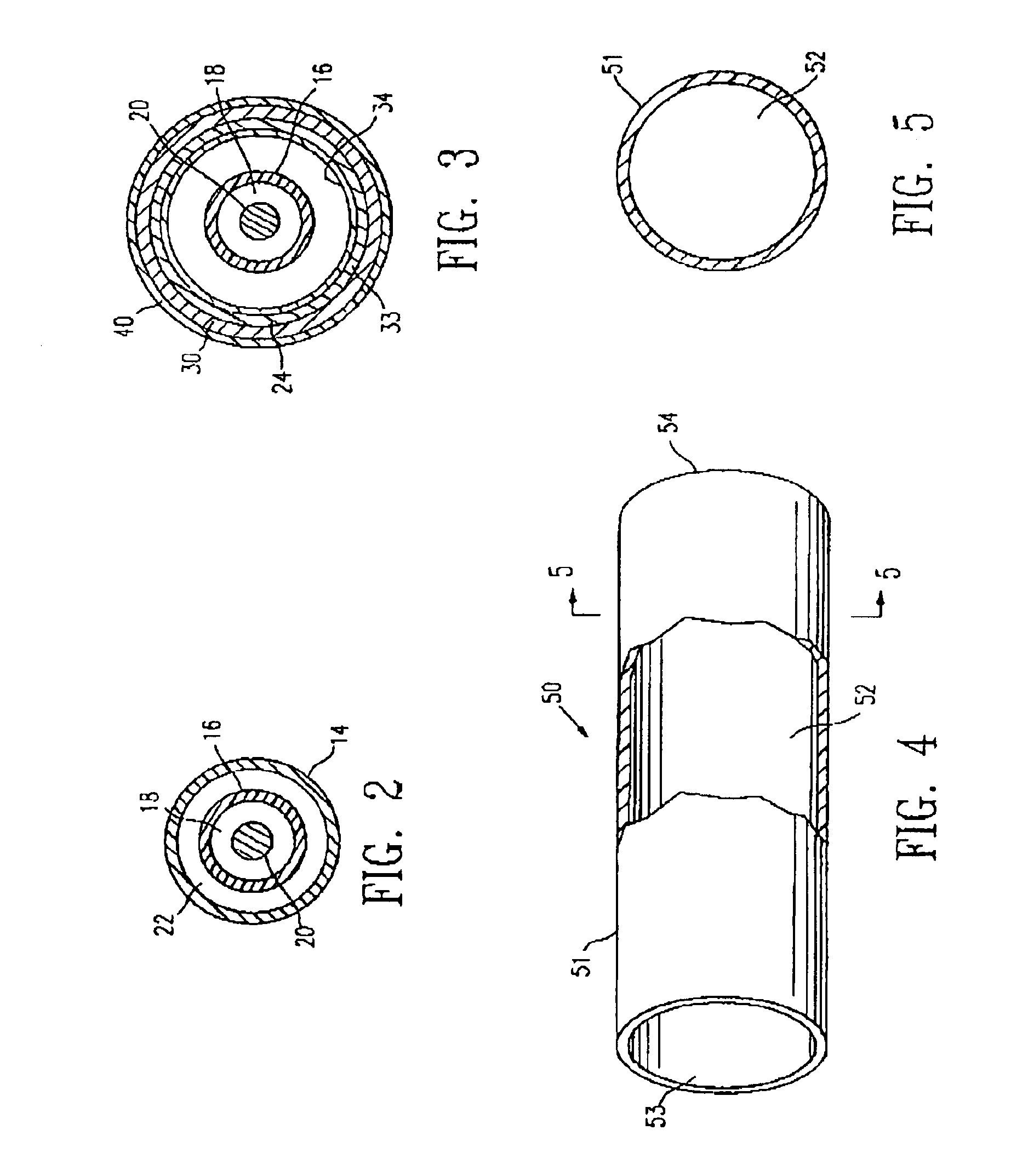
[0019]FIGS. 1-3 illustrate an over-the-wire type stent delivery balloon catheter 10 embodying features of the invention. Catheter 10 generally comprises an elongated catheter shaft 12 having an outer tubular member 14 and an inner tubular member 16. Inner tubular member 16 defines a guidewire lumen 18 adapted to slidingly receive a guidewire 20, and the coaxial relationship between outer tubular member 14 and inner tubular member 16 defines annular inflation lumen 22 (see FIGS. 2 and 3, illustrating transverse cross sections of the catheter 10 of FIG. 1, taken along lines 2—2 and 3—3 respectively). An inflatable balloon 24 is disposed on a distal section of catheter shaft 12. Balloon 24 has a proximal shaft section sealingly secured to the distal end of outer tubular member 14 and a distal shaft section sealingly secured to the distal end of inner tubular member 16, so that its interior is in fluid communication with inflation lumen 22. An adapter 26 at the proximal end of catheter ...


PUM

PropertyMeasurementUnit
Fractionaaaaaaaaaa
Fractionaaaaaaaaaa
Percent by massaaaaaaaaaa

Abstract

Medical devices or components thereof, and particularly intracorporeal devices for therapeutic or diagnostic uses, which are formed at least in part of a polymeric material and a ferromagnetic or paramagnetic material, so that the medical device or component thereof is visible on magnetic resonance imaging (MRI) scans. In one embodiment, the medical device is a balloon catheter having an MRI visible balloon. In a presently preferred embodiment, there is an insufficient amount of the ferromagnetic or paramagnetic material within a wall of the balloon or coated onto a wall of the balloon to make the balloon radiopaque.

Description

BACKGROUND OF THE INVENTION[0001]This invention generally relates to medical devices, and particularly to intracorporeal devices for therapeutic or diagnostic uses such as balloon catheters, and vascular grafts.[0002]In percutaneous transluminal coronary angioplasty (PTCA) procedures, a guiding catheter is advanced until the distal tip of the guiding catheter is seated in the ostium of a desired coronary artery. A guidewire, positioned within an inner lumen of a dilatation catheter, is first advanced out of the distal end of the guiding catheter into the patient's coronary artery until the distal end of the guidewire crosses a lesion to be dilated. Then the dilatation catheter having an inflatable balloon on the distal portion thereof is advanced into the patient's coronary anatomy, over the previously introduced guidewire, until the balloon of the dilatation catheter is properly positioned across the lesion. Once properly positioned, the dilatation balloon is inflated with fluid on...

Claims


Application Information

Patent Timeline
IPC IPC(8): A61L29/00A61M25/10A61L29/10A61L29/12A61L29/18A61B19/00A61M29/02A61F2/958
CPCA61F2/95A61L29/106A61L29/126A61L29/18A61M25/1029A61M25/104A61M25/10A61B2019/5454A61M2025/1079A61M2025/1031A61M2025/1075A61B2090/3954
Inventor LEE, JEONG S.WANG, EDWINWHITE, ROSEMINDA J.ROMERO, JOSE A.
Owner ABBOTT CARDIOVASCULAR
Why Eureka
Try Eureka