
Vehicle rooftop engine cooling system

a technology for cooling systems and engine compartments, which is applied in the direction of instruments, lighting and heating apparatus, process and machine control, etc., can solve the problems of difficult engine maintenance, difficult maintenance of engine or other engine compartment components, and large vehicles such as motor homes and delivery vans, so as to improve the efficiency of the engine cooling system used

Inactive Publication Date: 2005-06-28
SHEPPARD MULLIN RICHTER & HAMPTON
View PDF25 Cites 25 Cited by
  • Summary
  • Abstract
  • Description
  • Claims
  • Application Information

AI Technical Summary

Benefits of technology

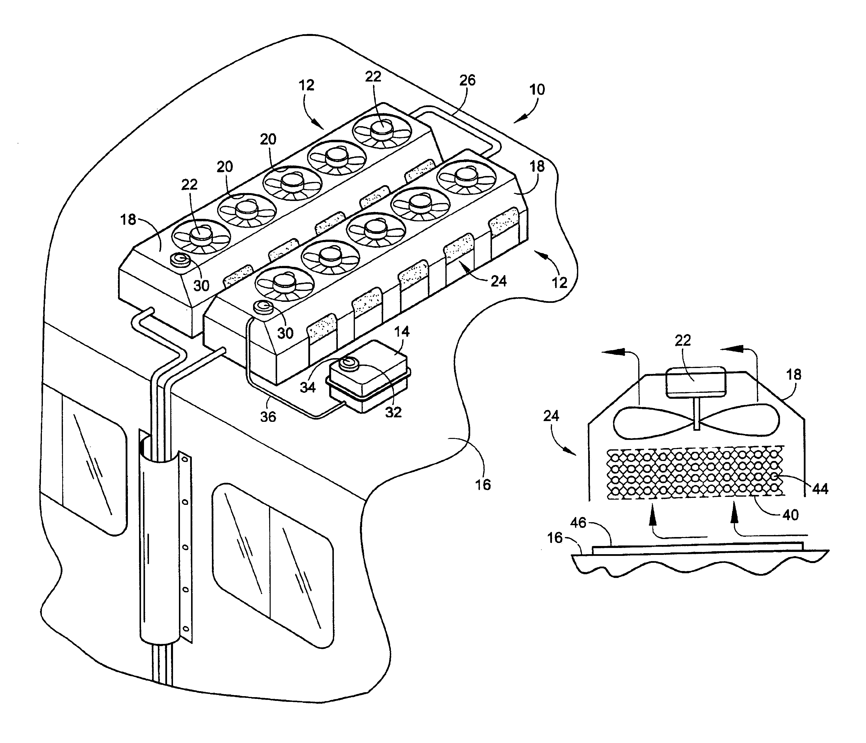
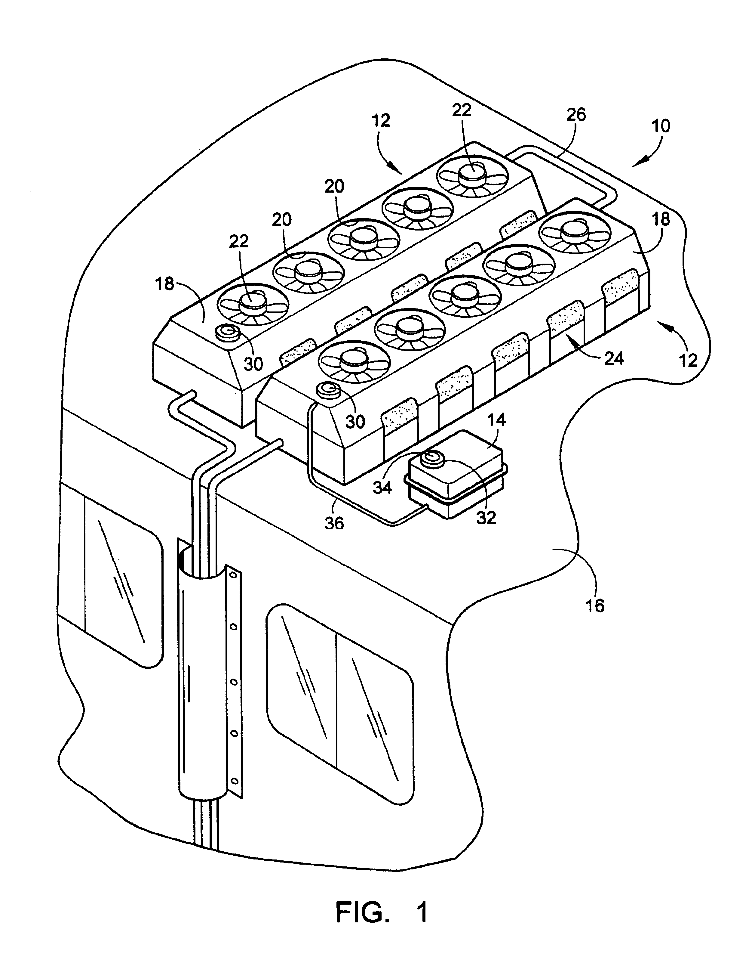
[0005]Accordingly, an aspect of the invention relates to a new and unique vehicle rooftop engine cooling system that improves the efficiency of present engine cooling systems used on buses. The engine cooling system includes one or more radiator units that are preferably horizontally oriented on the rooftop of a bus. Interconnected tubing connects the engine in the engine compartment to the one or more radiator units on the rooftop of a vehicle.
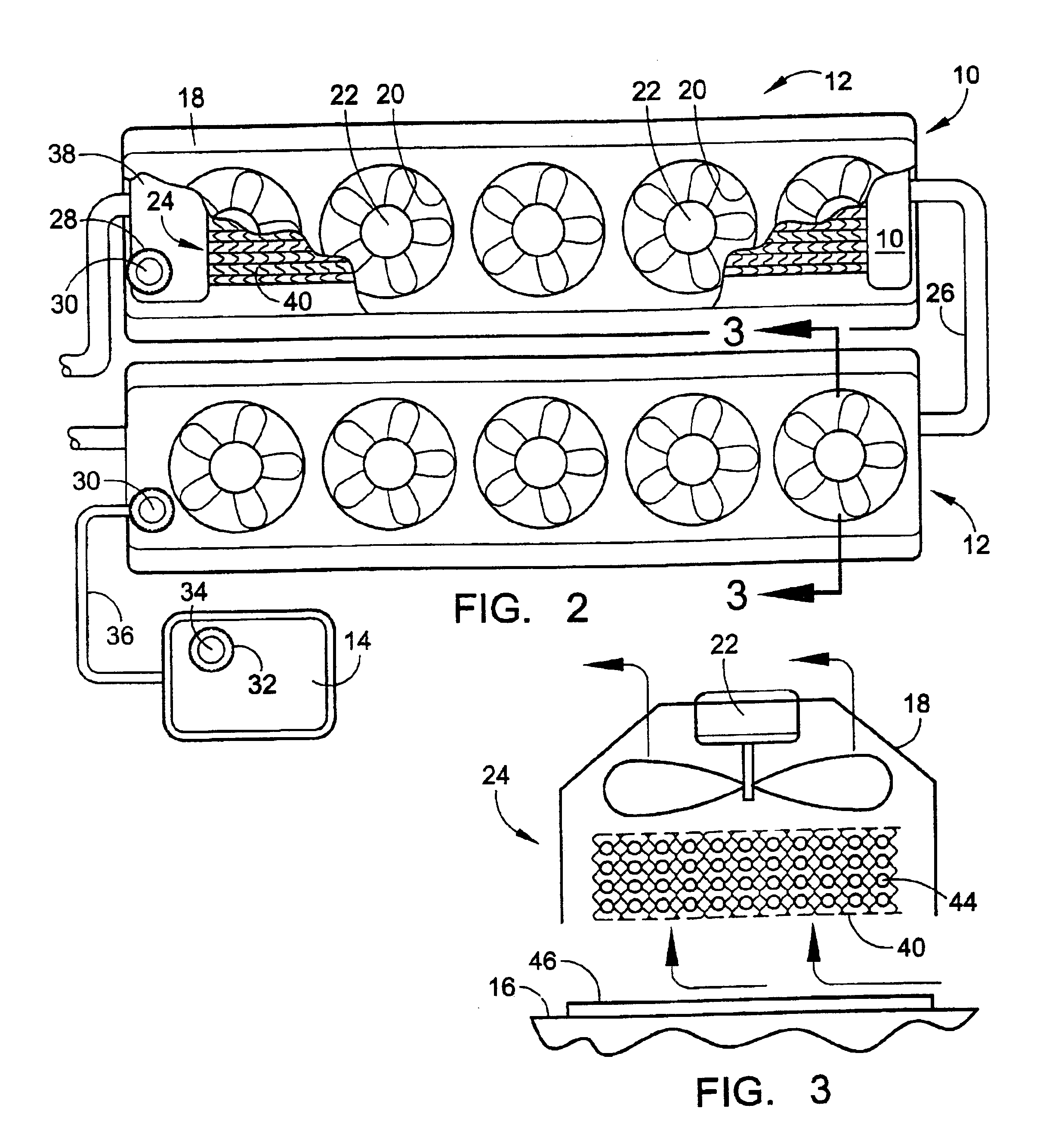
[0006]Horizontally orienting the one or more radiator units on the rooftop of a vehicle reduces the power load of the radiator fans on the internal combustion engine and / or battery. The horizontal rooftop engine cooling system may include electrically driven, thermostatically controlled fans to assist in cooling the rooftop engine cooling system. The large surface area of the roof top of the bus significantly reduces the fan power requirement by more than a factor of ten compared to a standard radiator in an engine compartment. Standard bus radiators / intercoolers consume up to 50 HP of engine power to drive the radiator cooling fan alone. The electrically driven radiator fans used with the horizontal rooftop engine cooling system consume less than 3 HP of engine power for equivalent cooling. The larger surface area of the roof top reduces the required airspeed through the radiator units and the required air pressure drop across the radiator units, thus, increasing the cooling system efficiency of the radiator units.
[0007]The horizontal rooftop engine cooling system also allows for natural convection air current to rise through the radiator units in an unconfined area. With the radiator unconfined on the rooftop of the vehicle, and with less demanding size limitations, the heat may be dissipated in a natural upward direction, minimizing the use of the electrically driven, thermostatically controlled fans. Consequently, the load of the electrically driven, thermostatically controlled fans is far less than that of fans of a standard radiator located in the engine compartment of a vehicle or even hydraulically powered fans mounted vertically on the rooftop.
[0008]A further benefit of locating the cooling system horizontally on the rooftop of the vehicle is that some of the cleanest and coolest air is available at the altitude of the rooftop, reducing the number of times the radiator needs to be serviced and increasing the duration between radiator cleanings. Because radiator cleaning requirements stipulate that the radiator be cleaned in the opposite direction of the airflow, the cooling system can be cleaned by simply spraying water through the fan orifices and shroud openings from outside of the cooling system. This type of cleaning would occur each time the bus passes through a normal bus wash cycle without any component disassembly. This is much simpler and less time-consuming than cleaning a radiator from the inside of the engine compartment, which may require partial disassembly of the radiator shroud to effectively clean the radiator.

Problems solved by technology

The location of the radiator often makes it difficult to perform maintenance on the engine.
Large vehicles such as buses, motor homes, and delivery vans have limited frontal access to the engine compartment that is often partially or completely blocked by the radiator of the vehicle.
This can make maintenance on the engine or other engine compartment components very difficult.
This low mounting location increases the dirt and debris collected by the radiator, and, hence, increases the number of times the radiator needs to be cleaned and checked, and decreases the cleaning intervals.
This may require partial disassembly of the radiator shroud to effectively clean the radiator, increasing the time and complexity of the radiator cleaning process.

Method used


Image

  • Vehicle rooftop engine cooling system
  • Vehicle rooftop engine cooling system
  • Vehicle rooftop engine cooling system

Examples


Embodiment Construction

[0016]With reference to FIG. 1, an embodiment of a horizontal rooftop engine cooling system 10 will be described. The horizontal rooftop engine cooling system 10 is preferably implemented on a rooftop 11 of a bus; however, it should be fully understood that the rooftop engine cooling system 10 may be applied to the rooftop of any vehicle propelled by a propulsion system requiring cooling. Further, the rooftop engine cooling system 10 may be incorporated into new vehicles or may be a retrofitted onto existing vehicles.

[0017]The rooftop engine cooling system 10 may include one or more horizontal radiator units 12 and an optional overflow tank 14 located on the rooftop 11 of a vehicle 16. Each horizontal radiator unit 12 may include one or more types of shrouds 18 having one or more fan orifices 20 and one or more respective electrically driven, thermostatically controlled fans 22 housed over a radiator 24.

[0018]The type of shroud 18 can be for fan mounting, aerodynamic air-flow, or or...


PUM


Abstract

A horizontal rooftop engine cooling system includes one or more radiator units horizontally mountable to the rooftop of a bus and including a radiator interconnected to one or more passages of an engine of the bus to allow coolant to flow between the engine and the rooftop cooling system to cool the engine. The cooling system can incorporate a fan mounting shroud, a ram-air aerodynamic shroud, and / or an ornamental aesthetic appearance shroud.

Description

FIELD OF THE INVENTION[0001]The field of the invention relates, in general, to systems and methods for cooling motor vehicle engines, and, in particular, to systems and methods for cooling motor vehicle engines of buses.BACKGROUND OF THE INVENTION[0002]Some type of radiator or heat exchanger is normally required to remove heat from an internal combustion engine. For most applications, the power required to turn the fan that moves air through the radiator has been obtained through some mechanical, hydraulic, or belt-driven connection to the engine crankshaft.[0003]A conventional radiator includes an intake tank, a core made up of a plurality of finned tubes, and an exit tank connected by hoses. The radiator may be used to cool the means of propulsion (e.g., gas engine, diesel engine, fuel cell engine) in the motor vehicle. The radiator may be filled with a coolant to radiate superfluous heat from the engine into the air by means of conduction and convection. Fans, which may be powere...

Claims


Application Information

Patent Timeline
IPC IPC(8): B60K11/04B60K11/02F01P3/00F01P3/18F28F9/00F28D1/04F01P7/00F01P11/00F01P7/08F01P11/06F01P5/02
CPCB60K11/04F01P3/18F28F9/001F28D1/04F01P7/08F01P2011/063F01P2005/025
Inventor STONE, KEVIN THOMASSCHULTE, JUERGEN
Owner SHEPPARD MULLIN RICHTER & HAMPTON
Learn More