Airflow control device

Inactive Publication Date: 2005-06-28
ILLINOIS TOOL WORKS INC
View PDF33 Cites 27 Cited by
  • Summary
  • Abstract
  • Description
  • Claims
  • Application Information

AI Technical Summary

Benefits of technology

[0012]An advantage of the present invention is providing a simple yet reliable damper that is easy to install and reliable in operation for an extended useful lifetime.
[0013]Another advantage of the present invention is providing a damper that is compact and relatively inexpensive to install and operate.
[0014]Yet another advantage of the present invention is providing a damper having simple yet reliable heater means for eliminating frost over and insuring reliable damper operation in cold environments, such as found in a refrigerator.
[0015]Still another advantage of the present invention is providing a strong, compact activation mechanism that is easy to control and operate.
[0016]Other features and advantages of the invention will become apparent to those skilled in the art upon review of the following detailed description, claims and drawings in which like numerals are used to designate like features.

Problems solved by technology

While some minimal control results, the refrigerated compartment is not truly temperature controlled, and will become colder or warmer under various operating and use conditions of the refrigerator.
For example, if the refrigerated compartment is opened frequently and the damper is positioned for substantially restricted flow, insufficient airflow from the freezer compartment will result in the refrigerated compartment becoming warm.
A disadvantage is the relative inaccuracy of the temperature control provided thereby.
Thus, if the refrigerated compartment door is opened frequently, or left open for long periods of time such that the compartment warms, the refrigerant will expand, causing the damper to open.
As the refrigerated compartment cools, the refrigerant contracts, in turn causing the damper to close.
Disadvantages of systems of this type include the cost and complexity of the system, wider than desirable temperature swings in the refrigerated compartment, and the disadvantage of using a toxic fluid in the control system.
Drawbacks to known systems of this type include the relative complexity of the system and the cost associated with it.
Nevertheless, severe frost over can cause the damper to malfunction and can result in damage.
Systems of this type are undesirably large, reducing the space available for storing food.

Method used


Image

  • Airflow control device
  • Airflow control device
  • Airflow control device

Examples


Embodiment Construction

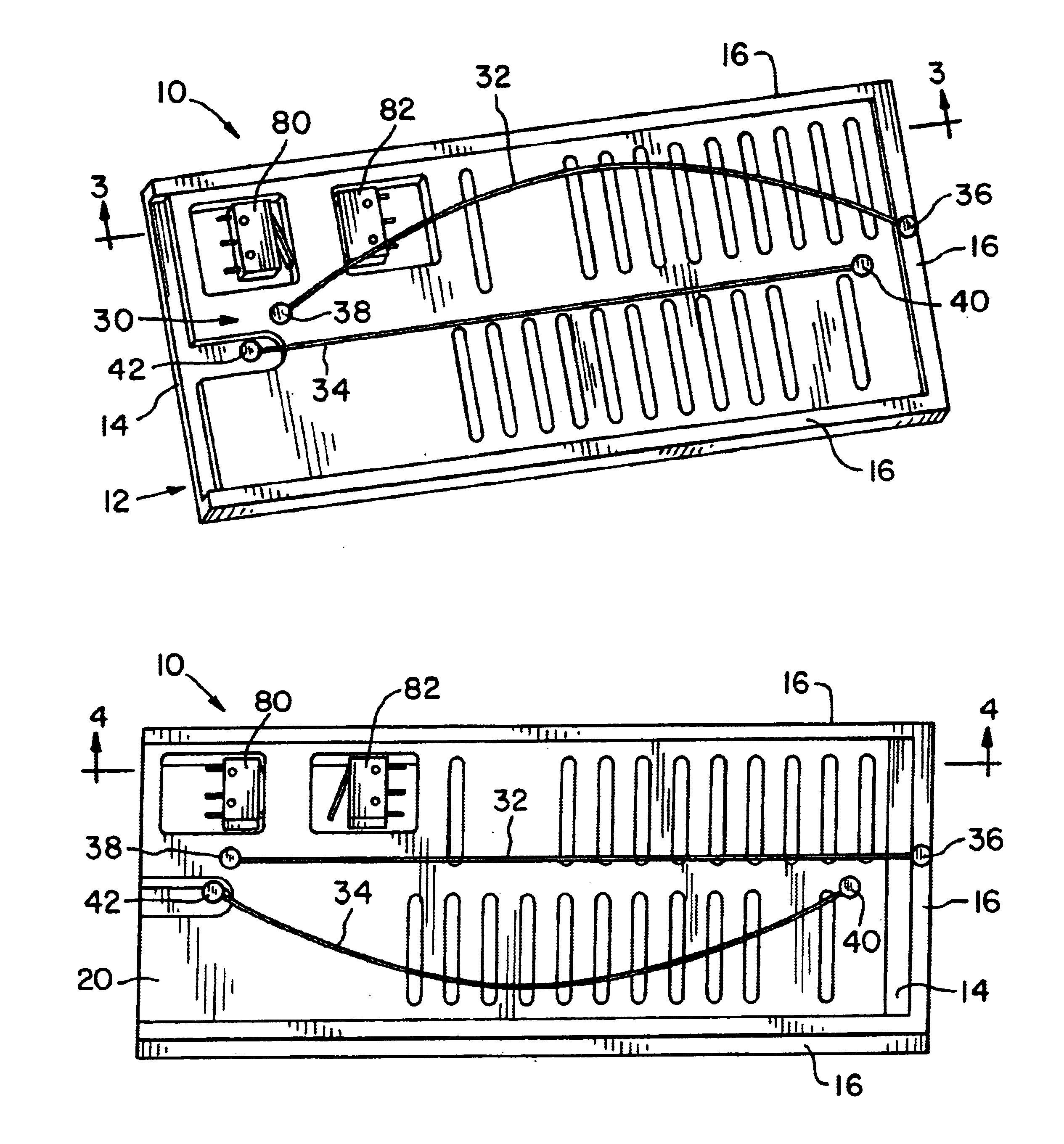
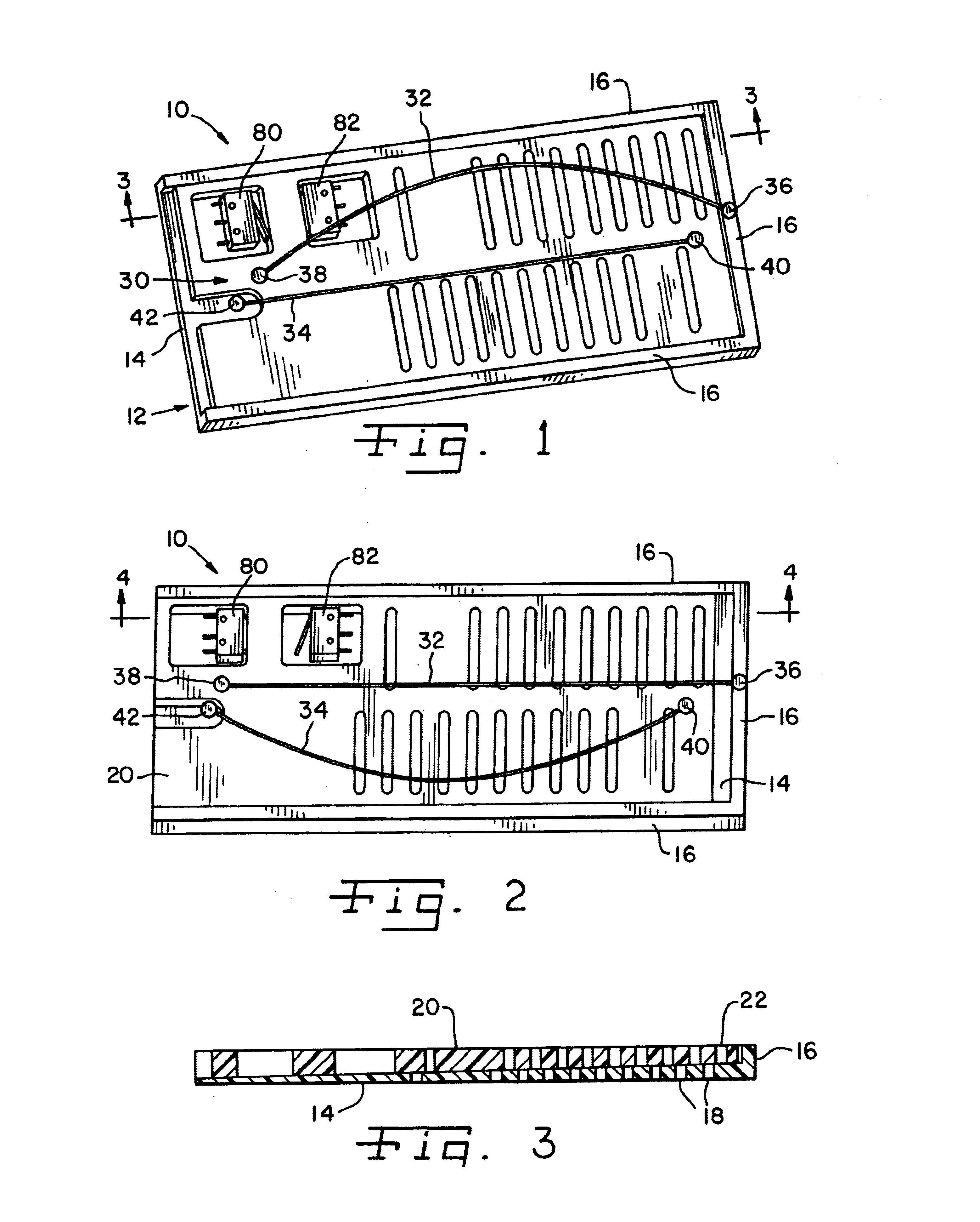
[0027]Referring now more specifically to the drawings and to FIG. 1 in particular, numeral 10 designates a damper in accordance with the present invention. Damper 10, as shown and described below, is provided in an airflow duct between a refrigerated compartment and a freezer compartment of a refrigerator. Those skilled in the art will understand that damper 10 may operate directly in an opening provided in a wall between the refrigerator and freezer compartments, or damper 10 may operate in a duct directing airflow from the freezer compartment to the refrigerated compartment. Flow through damper 10 may be natural airflow, or flow therethrough may be induced by a fan or other air moving device. It should be noted that although the invention is described in connection with a refrigerator, the invention is capable of use in other airflow control applications, and a refrigerator is merely shown and described as an example of one such application.

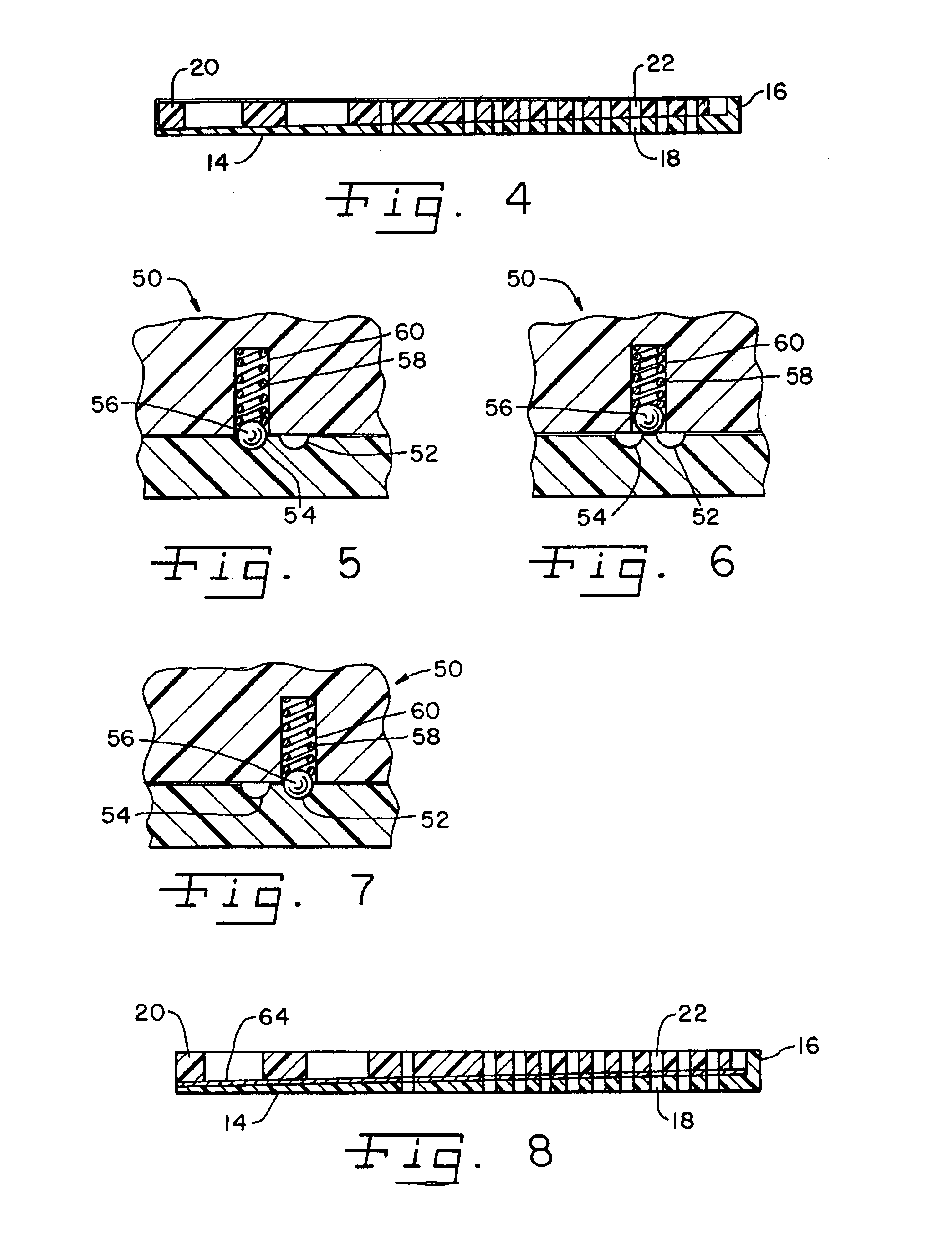
[0028]Damper 10 includes a first damper ...


PUM


Abstract

An airflow control device has a fixed damper element and a movable damper element. Shape memory wires are connected to the fixed damper element and the movable damper element. The shape memory wires are alternately electrified to cause the contraction thereof to move the movable damper element in opposite directions. A heater can be provided along with the damper elements to overcome frost buildup in cold environments, such as refrigeration systems.

Description

CROSS-REFERENCE TO RELATED APPLICATIONS[0001]This application claims benefit to U.S. Provisional Patent Application Ser. No. 60 / 373,040, filed on Apr. 16, 2002.FIELD OF THE INVENTION[0002]The present invention relates generally to airflow control devices, and, more particularly to dampers for regulating the flow of air between one compartment and another compartment, such as for example, between a freezer section and a refrigerated section of a refrigerator.BACKGROUND OF THE INVENTION[0003]There are many known airflow control devices for regulating the flow of air from one area to another area. In regards to refrigerators in particular, known refrigerator arrangements utilize a compressor refrigeration system for chilling the environment within the freezer compartment of the refrigerator. The refrigerated food compartment of the refrigerator is cooled by moving cold air from the freezer compartment into the refrigerated compartment. An airflow damper is provided between the refriger...

Claims


Application Information

Patent Timeline
IPC IPC(8): F25D17/04F24F13/10F24F13/12
CPCF25D17/045F24F13/12
Inventor NOWAK, DAVID R.DAM, ROBERTCARINGELLA, ANTHONY
Owner ILLINOIS TOOL WORKS INC
Why Eureka
Try Eureka