
Baler

a baler and spherical technology, applied in the field of balers, can solve the problems of additional manufacturing costs, and achieve the effect of accelerating the drying process or measuring the condition

Active Publication Date: 2005-06-28
DEERE & CO
View PDF17 Cites 14 Cited by
  • Summary
  • Abstract
  • Description
  • Claims
  • Application Information

AI Technical Summary

Benefits of technology

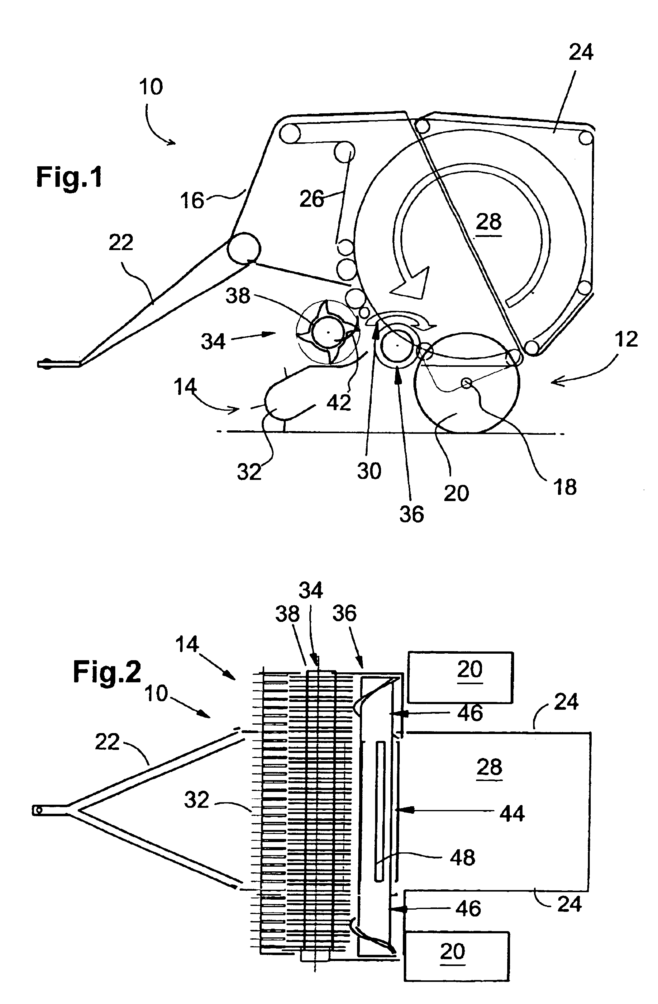
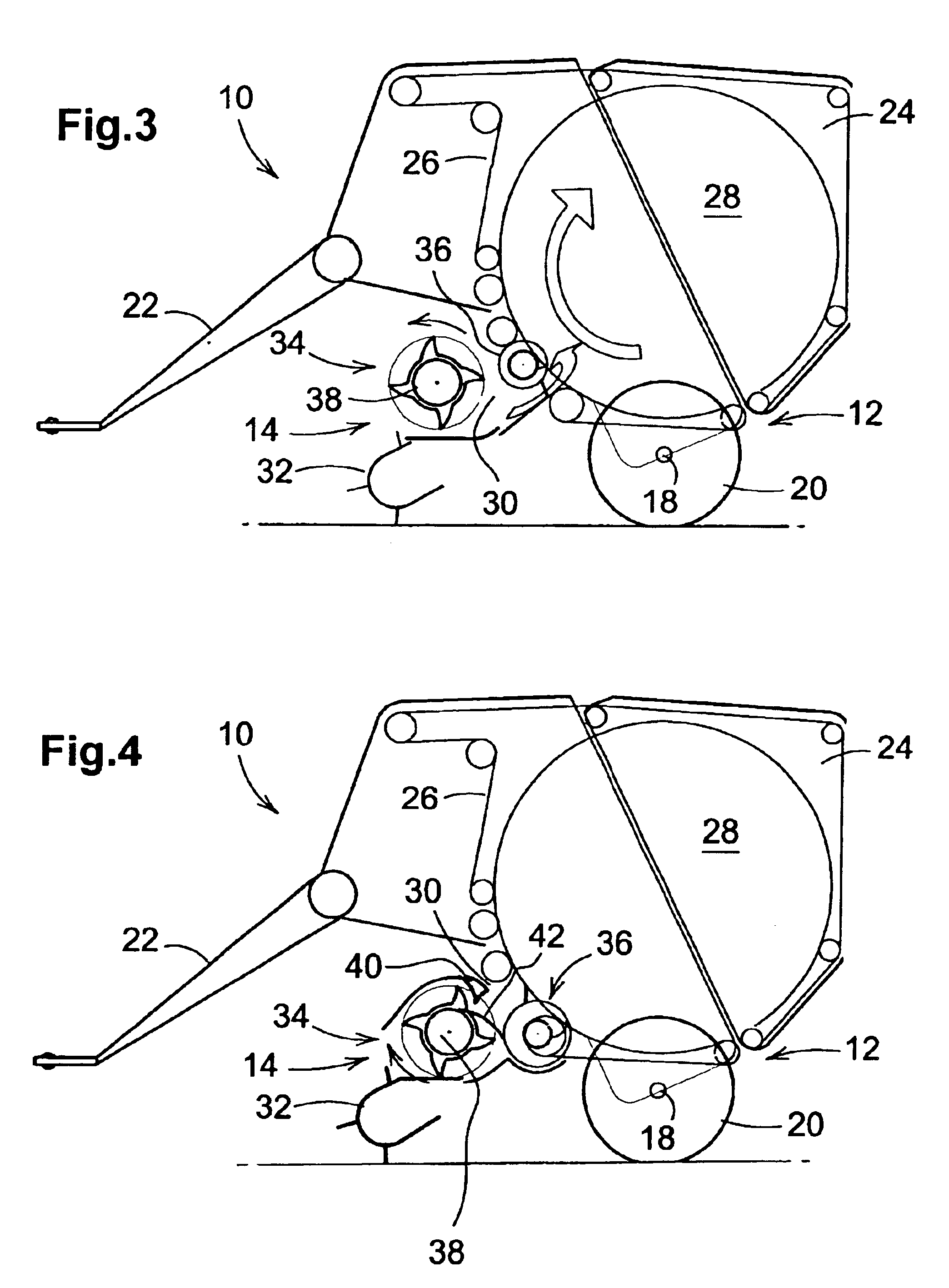
[0006]In this way, the flow of the crop that must be accommodated by the crop processing arrangement is accepted by the crop take-up device uniformly and in a relatively thin mat, and can be delivered further without any trouble. As soon as the crop is processed, for example, cut, moistened, conditioned or the like, and is combined safely in a mat, it can be delivered further without any problems to the transverse conveyor that conducts it further directly into the baling chamber or a pre-compression chamber.
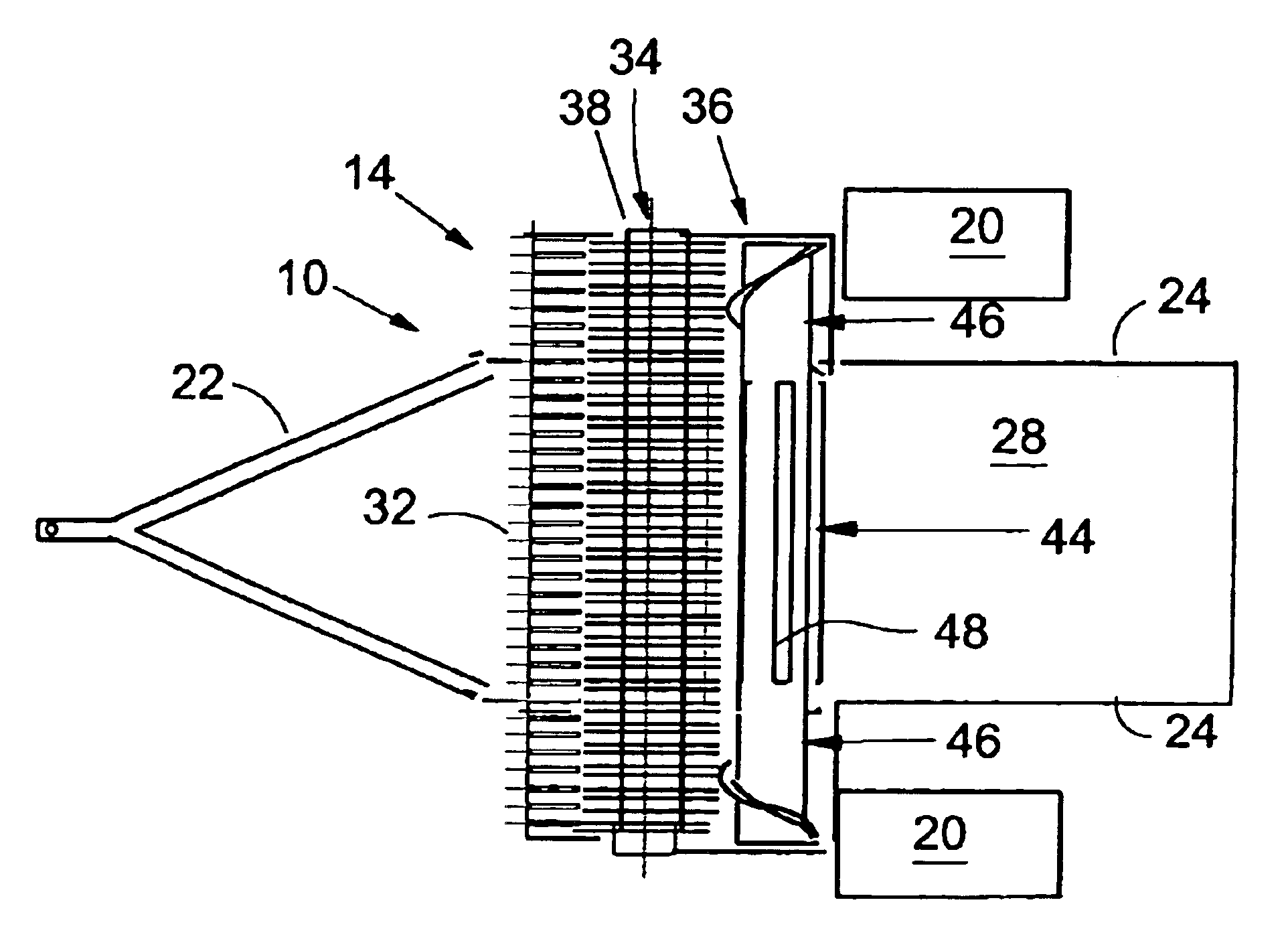
[0010]Although a transverse conveyor can be configured in a multitude of ways, for example, with a rotor rotating about a generally vertical axis; but it is simpler and more cost effective to use screw conveyors or stub screw conveyors that are oriented along an axis perpendicular to the direction of the flow of crop. This orientation also corresponds to that of the take-up device and the conveyor, so that the drive can be performed over gears, sprockets, belt pulleys, etc., located in a single plane.
[0012]If the projecting sections or if the projection is located only on one side, this section is driven slower or faster than the remainder so that the flow of the crop to the baling chamber can be improved.
[0015]Drivers on the section of the transverse conveyor facing the baling chamber have the advantage that they actively support the conveying of the crop to be baled into the baling chamber, and if necessary, also support the rotation of a cylindrical bale in a large round baler. These drivers may be configured as rails, fingers, tines bridges, etc., that are arranged rigidly or so as to retract and project in or on a rotor.
[0016]In particular, the configuration of the crop processing arrangement as cutter head, squeezing device, moistening arrangement or analysis arrangement brings about considerable advantages, since there a thin, uniform mat contributes significantly to the success of the cut, steaming of the dry alfalfa, squeezing of closed stalks to accelerate the drying process or the measurement of the condition of the crop or its contents.

Problems solved by technology

Up to the compression of the harvested crop in a silo or a wagon, further following components are included that cause additional manufacturing costs.

Method used


Image

  • Baler
  • Baler
  • Baler

Examples


Embodiment Construction

[0025]Referring now to FIG. 1, there is shown a baler 10 having a chassis 12 and a crop supply assembly 14. The baler 10 is configured as a large round baler, which however, is not mandatory. Rather, the baler could be configured as a rectangular baler for producing large parallelepiped bales. The baler 10 is applied on the field and takes up crop deposited on the ground in wide swaths, in order to subject it to a baling process. In the case of a large round baler, a configuration with a baling chamber of fixed size as well as a chamber of variable size can be considered.

[0026]The chassis 12 includes a frame 16, an axle 18 with wheels 20, a towbar 22, side walls 24 and a baling arrangement 26. The frame 16 is typical in that it consists of the principal components that are bolted or welded together for carrying the aforementioned components. The axle 18 forms the connection between the wheels 20 and the frame 16 and can be attached or configured as spring-supported or rigidly. The w...


PUM


Abstract

A large round baler is equipped with a plurality of components for delivering crop to an inlet of a baling chamber of a large round baler. These components have a width which is substantially wider than the baling chamber inlet and include a crop take-up device and a crop processing arrangement, such as a cutter head, that receives crop from the crop take-up device. The crop processing arrangement delivers the processed crop to a transverse conveyor, which narrows the stream of crop to the width of the baling chamber inlet.

Description

FIELD OF THE INVENTION[0001]The invention concerns a baler with a take-up device, crop processing arrangement and transverse conveyor following each other in the direction of flow.BACKGROUND OF THE INVENTION[0002]Known large round balers and rectangular balers receive the crop to be baled from a take-up device of great width that delivers it to a transverse conveyor, such as a screw conveyor, that conducts it in turn selectively into a cutter head from which it reaches a baling chamber. An example of such a baler is disclosed in DE 198 06 630.[0003]The problem underlying the invention is seen in the fact that the condensed and compressed crop to be baled can bring about jams in the cutter head.SUMMARY OF THE INVENTION[0004]According to the present invention, there is provided a novel combination of components for use in picking up crop and transporting it to an inlet of a baling chamber.[0005]An object of the invention is to provide a series of components ahead of a baling chamber t...

Claims


Application Information

Patent Timeline
Patent Type & Authority Patents(United States)
IPC IPC(8): A01D90/04A01D90/00A01F15/10A01F15/00
CPCA01F15/106A01D90/04
Inventor VIAUD, JEAN
Owner DEERE & CO
Learn More