
Broad band antenna

a broad band antenna and antenna technology, applied in the direction of antennas, antenna supports/mountings, radiating element structural forms, etc., can solve the problems of adding to the complexity of the antenna and hence the cost of manufacture, and achieve the effects of improving the phasing section of the inter-element, improving the broad band characteristics, and increasing the capacitan

Inactive Publication Date: 2005-06-21
RF IND
View PDF7 Cites 5 Cited by
  • Summary
  • Abstract
  • Description
  • Claims
  • Application Information

AI Technical Summary

Benefits of technology

"The present invention provides a series collinear antenna segment that can be curved in use, which improves its broad band characteristics compared to standard design segments. The curved substrate provides increased capacitance and a more improved inter-element phasing section. The use of a single flexible substrate allows for cost-efficient manufacturing techniques. The inter-element phasing sections and radiating elements are arranged so that they face perpendicular to each other, which improves performance. The inter-element phasing sections include a conductive track arranged to follow a serpentine path, which is a cost-effective technique for introducing phase differences between radiating elements."

Problems solved by technology

There is no need to incorporate secondary elements which add to the complexity of the antenna and hence to the cost of manufacture.

Method used


Image

  • Broad band antenna
  • Broad band antenna
  • Broad band antenna

Examples


Embodiment Construction

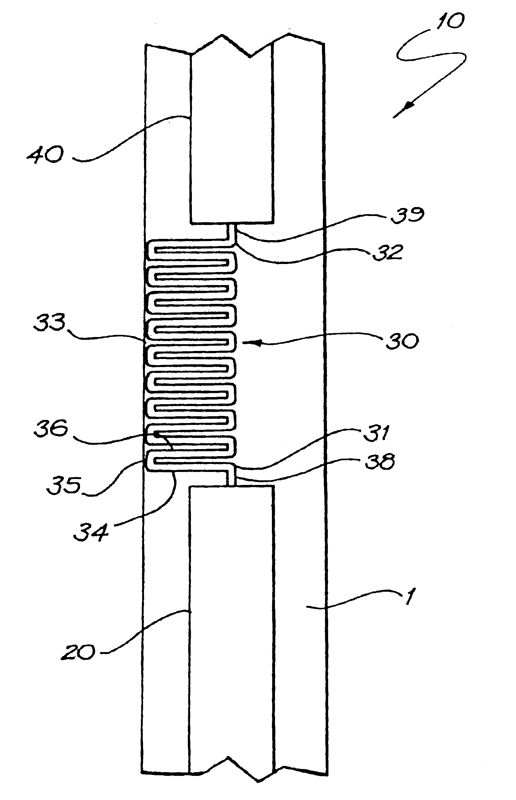
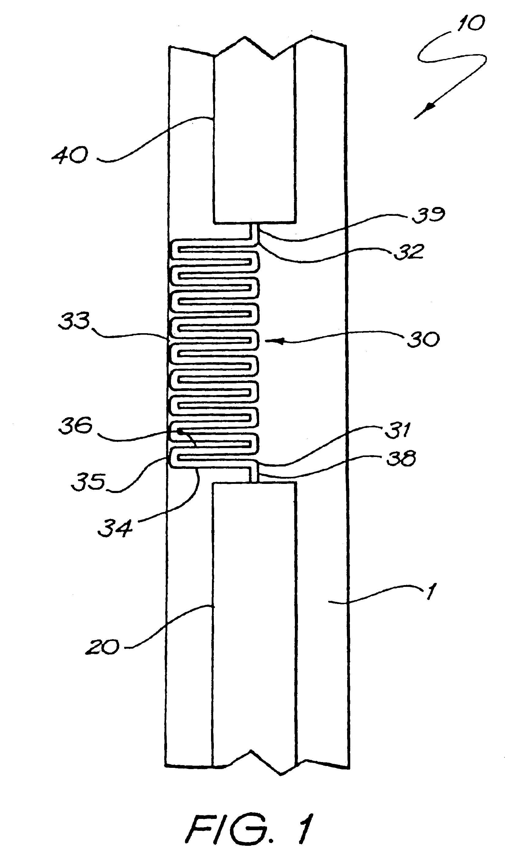
[0019]Referring now to FIG. 1 there is illustrated a series collinear antenna segment 10. The segment consists of a first radiating element 20, an inter-element phasing section 30 and a further radiating element 40 identical in dimension to the first radiating element 20. It is understood that further phasing sections and radiating elements may be added as is required. These elements consist of a conductive material such as copper disposed upon a single sided flexible continuous substrate 1. An example of a suitable substrate is standard flexible PCB material. In other embodiments the conductive material can be gold.

[0020]We will first consider the radiating elements 20 and 40. The geometry of a radiating element is primarily dependent upon the target design wavelength λ intended for the series collinear antenna segment. In this embodiment a segment suitable for use in an antenna designed for a target wavelength of 34 cm (equivalent frequency 890 MHz) and with a bandwidth of 15% is ...


PUM


Abstract

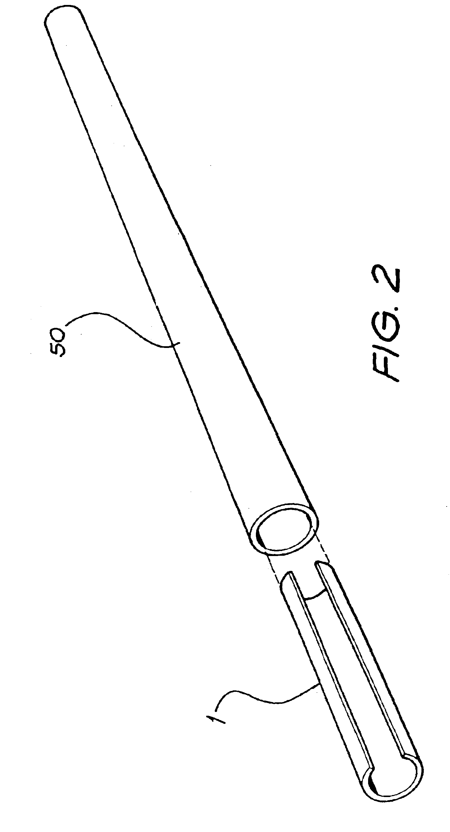
A collinear antenna segment is provided with a plurality of radiating elements and inter-element phasing sections arranged alternately on a singlesided elongated substrate. The segment has an operatively curved in-use configuration about a longitudinal axis running substantially along the length of the segment. In use, the inter-element phasing sections allow the radiating elements to radiate electromagnetic radiation substantially in phase over an intended range of frequencies. The segment may be arranged on a flexible substrate which can be operatively curved for insertion into a radome. Alternatively, the segment may be directly arranged on the curved inner surface of a radome.

Description

FIELD OF THE INVENTION[0001]The present invention relates to antenna devices, and, more particularly to collinear antennas.BACKGROUND OF THE INVENTION[0002]Series collinear antenna segments are well known in the field of antenna design. They have a number of advantages over other collinear antenna strategies such as a corporate feed collinear because of their ease of construction and associated affordability. They consist of a number of alternate radiating elements and inter-element phasing sections resulting in a phased array antenna.[0003]Each radiating element is optimally fed in phase so that each of the radiating elements will radiate in unison. This enables the focussing of the antenna radiation pattern. Each individual radiating element is designed to be of a specific physical length in order to provide the most effective radiation of power for a given wavelength. Following each active radiating element is an inter-element phasing section, wherein the radiation from the anten...

Claims


Application Information

Patent Timeline
Patent Type & Authority Patents(United States)
IPC IPC(8): H01Q5/00H01Q1/00H01Q1/36H01Q5/02H01Q1/40H01Q5/15H01Q9/00
CPCH01Q1/36H01Q9/40H01Q9/28H01Q1/40
Inventor WANG, DANIELDALY, ROBERTJAQUES, STEVE
Owner RF IND
Learn More