
Linear actuator

a linear actuator and actuator technology, applied in the direction of fluid couplings, pedestrian/occupant safety arrangements, transportation items, etc., can solve the problems of fluid leakage between stages, limited use, and fast wear of seals, and achieves small profile, long stroke, and light weight

Inactive Publication Date: 2005-06-21
AUTOLIV ASP INC
View PDF12 Cites 9 Cited by
  • Summary
  • Abstract
  • Description
  • Claims
  • Application Information

AI Technical Summary

Benefits of technology

The present invention provides a single-acting linear actuator that has a small profile but a long stroke, is inexpensive, light weight, reliable, maintenance free, self-contained, and deploys very rapidly. The actuator includes a wall, a piston, and a fluid generator. The piston is connected to the first end of the wall and extends along the axis of the wall. The actuator may have a plurality of piston stages that deploy in succession when a pressurized fluid is applied. The actuator may be manufactured using a variety of manufacturing processes. The technical effects of the invention include a small actuator size, a long stroke, low cost, light weight, reliability, maintenance-free operation, self-containment, and fast deployment.

Problems solved by technology

Unfortunately, linear actuators have limitations.
Friction between the stages and seals causes the seals to quickly wear.
Worn seals may cause fluid to leak between stages.
Thus, linear actuators having seals require periodic maintenance.
In addition, separate telescoping stages increase the assembly and production costs for the telescoping pistons.
However, the potential for leaks, cost of production and assembly, weight, rate of deployment and size may limit the applications of single-acting telescoping actuators.
Other linear actuators may only require a single reliable deployment of the piston.
Unfortunately, conventional single-acting linear actuators have been unable to meet the size, weight, reliability, rapid deployment, low profile and long stroke, and cost requirements for use in vehicle safety systems.

Method used


Image

  • Linear actuator
  • Linear actuator
  • Linear actuator

Examples


Embodiment Construction

[0038]The present invention can be better understood with reference to the drawings where like parts are designated with like numerals throughout.

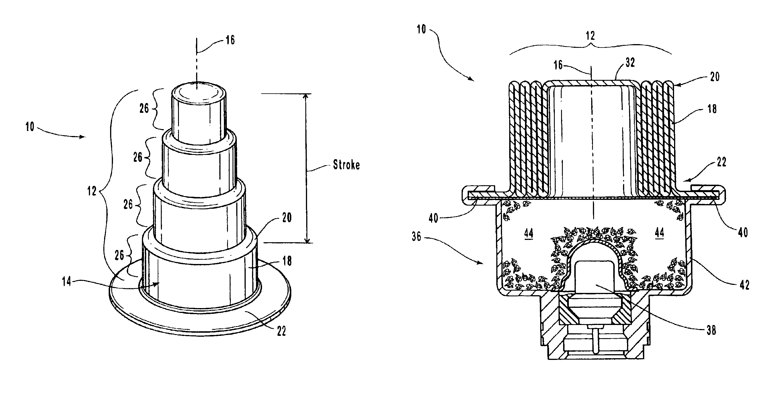
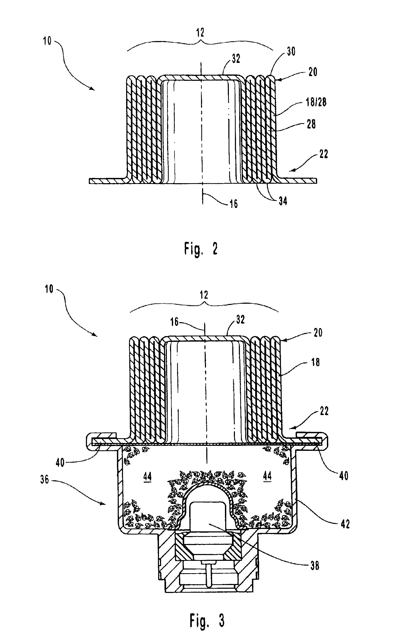
[0039]FIG. 1A illustrates one embodiment of a linear actuator 10 prior to deployment. The linear actuator 10 includes a piston 12 and housing 14. In a preferred embodiment, the housing 14 and piston 12 are integrated in a single piece. The piston 12 and housing 14 share a common longitudinal axis 16. The housing 14 includes a wall 18 which circumscribes the axis 16. The wall 18 encircles the piston 12 when the linear actuator 10 is not deployed. Preferably, the wall 18 runs parallel to the axis 16.

[0040]The wall 18 has a first end 20 and a second end 22. The second end 22 may be connected to a power source (not shown in FIG. 1A). Preferably, the first end 20 is integrated with the piston 12. Alternatively, the first end 20 may be connected to the piston 12. The first end 20 and piston 12 are joined such that fluid is unable to pass by the ...


PUM


Abstract

A linear actuator having a low profile and a long stroke is provided. The actuator includes a housing integrally connected to a telescoping piston. The piston may be extended by a fluid such as inflation gas provided by an inflation gas generator in fluid communication with the piston. The piston extends rapidly through a one-shot stroke. The extending piston converts energy in the fluid into motion for performing linear work. The linear actuator may be formed from a single piece of parent material through stamping processes including deep draw stamping. Alternatively, other metal forming processes may be used to form the linear actuator.

Description

BACKGROUND OF THE INVENTION[0001]1. The Field of the Invention[0002]The present invention relates to actuators. More specifically, the invention relates to a linear actuator having a low profile and a long stroke.[0003]2. Technical Background[0004]Actuators provide a very flexible and efficient mechanism for converting fluid power into linear or rotary motion. Power may be introduced into the fluid remotely and readily transferred to the actuator through fluid lines or channels. By transmitting power through the fluid, a uniform and constant mechanical motion can be achieved.[0005]While linear actuators include components which move linearly with respect to each other, combining a linear actuator with various gears, hinges, struts, and the like allows nonlinear movement of objects as well. Linear actuators have a broad range of applications. One common example of linear actuators are hydraulic lifts used on heavy equipment.[0006]Generally, a linear actuator includes a power supply, ...

Claims


Application Information

Patent Timeline
Patent Type & Authority Patents(United States)
IPC IPC(8): B60N2/42B60R21/34B60N2/427B60N2/23B60P1/16B60P1/04F15B15/00F15B15/16F15B15/10F15B15/19B60R21/00
CPCB60N2/231B60N2/42745B60P1/162F15B15/10F15B15/16F15B15/19B60R21/34B60R21/00B60R2021/23528B60R21/38
Inventor PARKS, BRENT
Owner AUTOLIV ASP INC
Learn More