
Starting of switched reluctance generators

a switched reluctance and generator technology, applied in the direction of single-phase induction motor starters, synchronous motor starters, dynamo-electric machines, etc., can solve the problems of unable to guarantee the charge of capacitors during prolonged shutdown, difficulty in providing storage batteries at that voltage, and additional costs

Inactive Publication Date: 2005-06-14
NIDEC SR DRIVES
View PDF19 Cites 3 Cited by
  • Summary
  • Abstract
  • Description
  • Claims
  • Application Information

AI Technical Summary

Benefits of technology

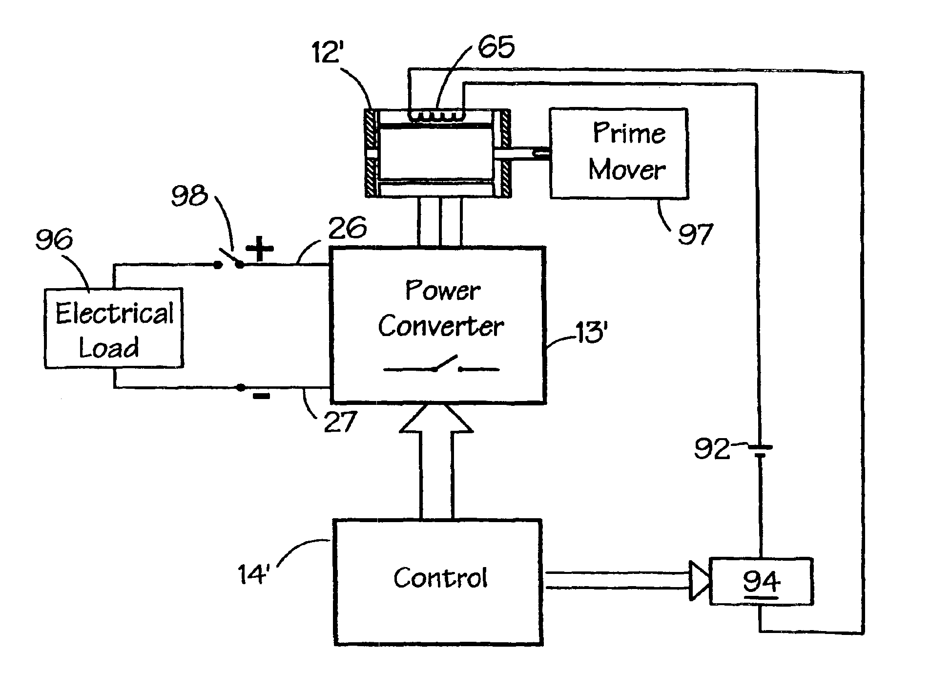
[0021]The reluctance machine may further comprise means for connecting the priming winding to a source of priming electrical energy, the connecting means comprising a switch, a chopper unit or a current controller. The priming winding and its associated priming power source, and switching components if any, optionally are rated for short-term use, so reducing the cost of implementation.

Problems solved by technology

However some systems are not part of a fixed installation because they are fitted on, for example, marine or automotive equipment, so a special source has to be provided.
In systems where the DC link has a high value (e.g. 300V or more), it is difficult to provide a storage battery at that voltage because of cost and safety implications.
This overcomes many of the safety problems associated with isolation of a high-voltage source, but is costly.
In addition, unless the up-converter is bi-directional, some other form of battery charging must be provided to re-charge the battery, entailing further cost.
Secondly, the system can rely on the short-term energy storage provided by the DC link capacitors in the power converter.
While this will be successful if the amount of charge left in the capacitors at the time of starting is sufficient to energize the machine adequately, there is no guarantee that the capacitors will hold their charge during a prolonged shutdown.
Further, it is often a requirement that capacitors are discharged before any maintenance work is done on the converter, and this would preclude subsequently starting the system by this method.

Method used


Image

  • Starting of switched reluctance generators
  • Starting of switched reluctance generators
  • Starting of switched reluctance generators

Examples


Embodiment Construction

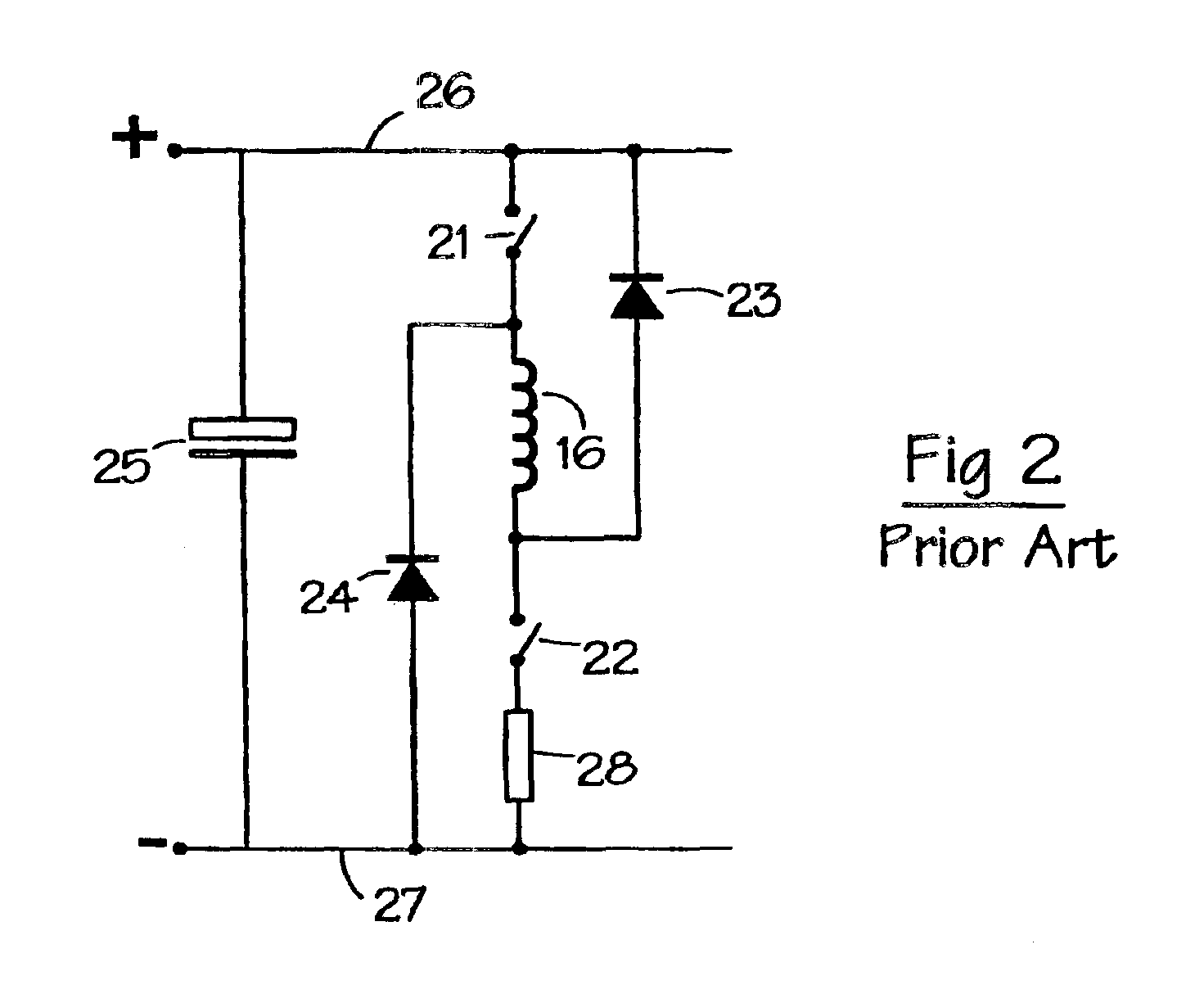
[0038]The Radun paper cited above discloses a starting method for a switched reluctance generator, whereby the excitation energy initially comes from a battery supplying an excitation bus for the phase windings of the machine. The generator returns all its output to that bus until the bus voltage rises to a suitable level, whereupon extra thyristor switches are closed to supply the output of the generator to the load. Steady state operation entails the use of both excitation buses and the extra thyristors. A similar system with split excitation and load buses is disclosed in European Patent Application No. 0564067, which is incorporated herein by reference.

[0039]By contrast with these prior art systems, embodiments of the present invention use a single bus and a separate priming winding which is used to pump up the voltage on the DC link capacitors. This is achieved by introducing initial flux linkage into the machine, thereby giving rise to a DC link voltage sufficient to enable th...


PUM


Abstract

A switched reluctance drive is operated as a generator on a high voltage supply which has no long-term energy storage capability. A low voltage supply is used to start the generator through the use of a dedicated priming winding, which provides sufficient energy to allow the generator to build up charge in DC link capacitor(s). Once sufficient charge has built up, the priming winding is de-energized and the generator continues in a steady-state operation.

Description

CROSS-REFERENCE TO RELATED APPLICATION[0001]The subject matter of this application is related to the subject matter of British Application No. 0215849.1, filed Jul. 9, 2002, priority to which is claimed under 35 U.S.C. § 119 and which is incorporated herein by reference.BACKGROUND OF THE INVENTION[0002]1. Field of the Invention[0003]The present invention generally relates to an apparatus and method for starting an electrical generating system. More particularly, the present invention relates to the operation of a switched reluctance generator for generating into a supply system which has no long-term energy storage capabilities.[0004]2. Description of Related Art[0005]The characteristics and operation of switched reluctance systems are well known in the art and are described in, for example, “The characteristics, design and application of switched reluctance motors and drives” by Stephenson and Blake, PCIM'93, Nürnberg, 21-24 Jun. 1993, incorporated herein by reference. FIG. 1(a) sh...

Claims


Application Information

Patent Timeline
Patent Type & Authority Patents(United States)
IPC IPC(8): H02P9/00H02P9/40H02K19/10H02P1/46H02P25/08H02P9/08
CPCH02K19/103H02P9/40H02K19/20H02P2101/45H02P1/46
Inventor TURNER, MICHAEL JAMES
Owner NIDEC SR DRIVES
Learn More