
Hand rasp with groove blade and adjustable guide for scoring construction material

a construction material and adjustable guide technology, applied in the direction of gear teeth, gear teeth, flat surface machines, etc., can solve the problems of requiring complete re-work of the area, messy application of subsequent coats, and economic waste, and achieves smooth starting of scoring or etching, increasing or decreasing distance, and great versatility in style and/or shape.

Active Publication Date: 2005-06-14
CASCIATO JR ANDREW
View PDF23 Cites 14 Cited by
  • Summary
  • Abstract
  • Description
  • Claims
  • Application Information

AI Technical Summary

Benefits of technology

[0021]It is a further object of the present invention to provide an improved hand rasp for scoring or etching grooves into cement or mortar finishes applied to EFIS as a final exterior coat.
[0030]The hand rasp, having a guide and a groove blade, provides a hand tool intended to score or etch insulation surfaces (like EFIS) with functional or decorative grooves, wherein the hand tool overcomes the deficiencies and shortcomings of the prior art discussed. In particular, the hand rasp with the guide and groove blade is easy to hold and manipulate, thereby reducing the potential for injury to a user or damage to the device or construction materials. The hand rasp does not require electricity, thus awkward electrical cords are avoided. The durability of the hand rasp, because of the metallic materials from which it is constructed, reduce cost and promote efficiency in the work environment. As such, and for the reasons previously described, the hand rasp disclosed and claimed in the present invention overcomes the deficiencies of hand tools presently available.

Problems solved by technology

Without starting / stopping points, the application of subsequent coats will appear messy and non-uniform, and may require complete re-work of the area.
However, each of the aforementioned categories of hand tool suffers from certain deficiencies that render such use economically wasteful (in terms of time spent and impreciseness of tools leading to waste of construction materials) and / or unintentionally dangerous to use as required.
These deficiencies are particularly acute and pronounced when construction proceeds at elevated heights, especially on scaffolding or extension ladders.
However, the time spent harnessing the user, positioning the user, and then releasing the user from the harness is an inefficient and ineffective expenditure of valuable resources to the construction company, both in finances and time.
Furthermore, to safely use these devices and precisely score the required grooves generally requires years of experience and expensive trial and error in coping with the conditions presented.
The electrical hot knife presents other additional problems as compared to manual hand tools.
At elevated working heights, the construction professional must negotiate the electrical cord, which often is approaching the professional from the feet and presents an increased likelihood of tripping or disconnecting the power from the hot knife.
The precision of the blades in forming grooves is ultimately in the skilled hands of a user, but often minor misjudgments result in irreparable damage to the insulation.
The imprecision of scoring insulation is further compounded if awkward angles of engagement are required, such as overhead use.
The necessity for repeated replacement of the blades creates additional expense, as each blade generally costs about twelve dollars ($12.00).
The deformation of the blades causes imprecise scoring of the insulation, causing further delays and additional expenses.
In addition, the blades are extremely hot and present potential burn injuries and / or damage to person or object during operation.

Method used


Image

  • Hand rasp with groove blade and adjustable guide for scoring construction material
  • Hand rasp with groove blade and adjustable guide for scoring construction material
  • Hand rasp with groove blade and adjustable guide for scoring construction material

Examples


Embodiment Construction

[0051]The best mode for carrying out the invention is presented in terms of its preferred embodiment, herein depicted within FIGS. 1 through 10.

[0052]1. Detailed Description of the Figures

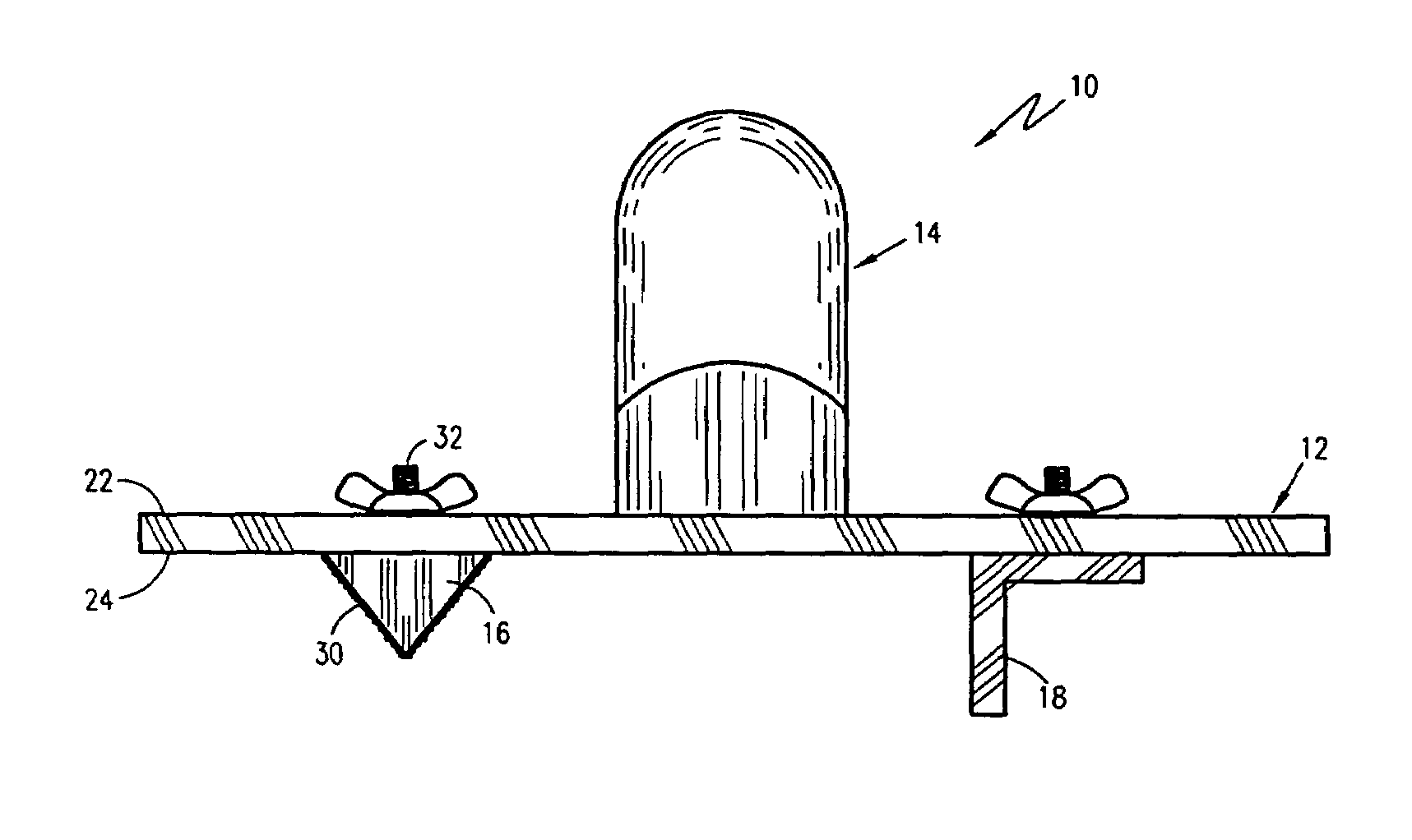
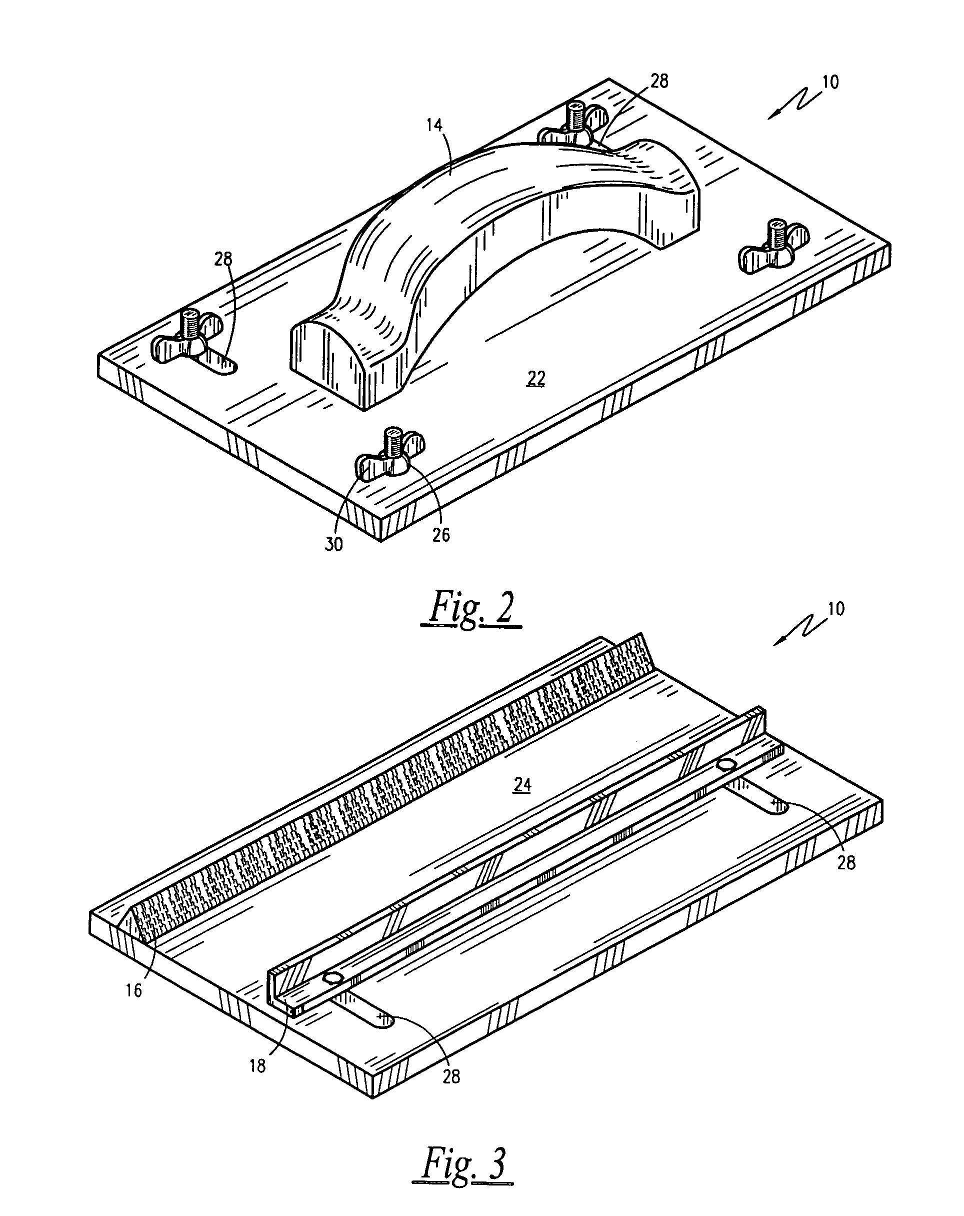
[0053]Referring now to FIG. 1 through FIG. 3, a hand rasp 10 is shown in accordance with a preferred embodiment of the present invention. The hand rasp 10 comprises a planar plate 12 having a grasping handle 14, a groove blade 16 and a guide 18 affixed to the plate 12. The hand rasp 10 scores a groove 50 (see FIG. 10) into an EFIS surface (60), or other similar surface, via the groove blade 16, thereby permitting a plurality of geometric configurations to be formed in a surface, the configurations having either decorative and / or functional grooves 50, which is then covered by at least one exterior coat or surface to exemplify and exaggerate the decorative or functional grooves 50 (as seen in FIG. 10).

[0054]The plate 12 comprises an anterior surface 22 and an opposing posterior surface 24 separate b...


PUM

PropertyMeasurementUnit
depthsaaaaaaaaaa
widthsaaaaaaaaaa
angleaaaaaaaaaa

Abstract

An improved hand rasp comprises a planar plate with an anterior surface and an opposing posterior surface. An ergonomic handle is affixed to the anterior surface of the plate. A groove blade is removably affixed to the posterior surface of the plate by attachment means. The groove blade may have a variety of geometric configurations and varying in width and depth to accommodate the imagination of the user or designer. The groove blade includes an abrasive surface on the exterior surface of the groove blade. A guide is also removably affixed to the posterior surface of the plate by attachment means, positioned parallel to the groove blade. The guide is adjustable about apertures formed in the plate to position the guide closer to or farther away from the groove blade.

Description

RELATED APPLICATIONS[0001]The present invention was first described in Disclosure Document Registration 515,541 filed on Jul. 25, 2002 under 35 U.S.C. §122, 37 C.F.R. §1.14 and MPEP § 1706. There are no previously filed, nor currently any co-pending applications, anywhere in the world.BACKGROUND OF THE INVENTION[0002]1. Field of the Invention[0003]The present invention relates generally to construction hand tools, and more particularly, a hand rasp with a groove blade for scoring surfaces, such as exterior insulation, so that functional and / or decorative grooves may be placed therein.[0004]2. Description of the Related Art[0005]A wide variety of hand tools have been developed and are currently available for scoring / etching grooves, and functional and / or decorative designs in construction material. Particularly, a variety of hand saws, rasps, utility knives and electrical hot knives are used to score, etch or groove exterior finish insulation systems (hereinafter “EFIS”) in preparati...

Claims


Application Information

Patent Timeline
Patent Type & Authority Patents(United States)
IPC IPC(8): B23D67/00B23D67/12B23D71/06
CPCB23D67/12B23D71/06Y10T407/1825
Inventor CASCIATO, JR., ANDREW
Owner CASCIATO JR ANDREW
Learn More