
Non-contact integrated circuit reader comprising a low power consumption active standby mode

a non-contact integrated circuit and active standby technology, applied in the field of data transmission by inductive coupling, can solve the problem of substantial de-tune of the antenna circuit of the reader

Inactive Publication Date: 2005-06-14
VERIMATRIX INC
View PDF3 Cites 44 Cited by
  • Summary
  • Abstract
  • Description
  • Claims
  • Application Information

AI Technical Summary

Benefits of technology

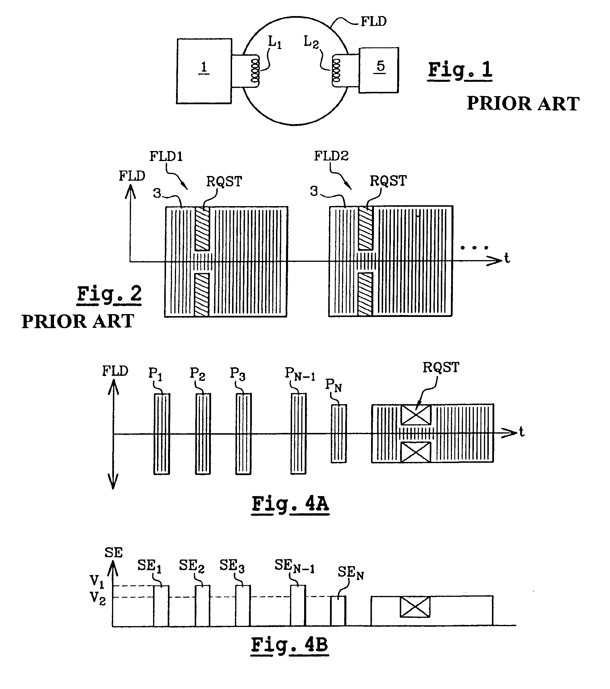
[0012]The present invention is based on the observation that the amplitude of the magnetic field emitted by a reader is substantially altered when the antenna coil of an integrated circuit is within the communication perimeter of the reader. Indeed, when a contactless integrated circuit is close to the reader, the antenna coil of the integrated circuit interferes with the coil of the reader (appearance of a mutual inductance), which substantially de-tunes the antenna circuit of the reader. Furthermore, it is well known that the amplitude of the magnetic field is easy to monitor by extracting an envelope signal from the antenna coil. Thus, one aspect of the present invention is to emit short magnetic field pulses, which only cause insignificant current consumption, and to observe the amplitude of the envelope signal. If, at a given instant, the amplitude of the envelope signal has a variation higher than a determined threshold or a determined attenuation, then, according to the present invention, that means that a contactless integrated circuit has just entered the communication perimeter of the reader.
[0030]According to one embodiment, the reader has a low current consumption active standby mode wherein the reader continually emits short magnetic field pulses and determines upon each pulse whether or not the integrated circuit is detected.

Problems solved by technology

Indeed, when a contactless integrated circuit is close to the reader, the antenna coil of the integrated circuit interferes with the coil of the reader (appearance of a mutual inductance), which substantially de-tunes the antenna circuit of the reader.

Method used


Image

  • Non-contact integrated circuit reader comprising a low power consumption active standby mode
  • Non-contact integrated circuit reader comprising a low power consumption active standby mode
  • Non-contact integrated circuit reader comprising a low power consumption active standby mode

Examples


Embodiment Construction

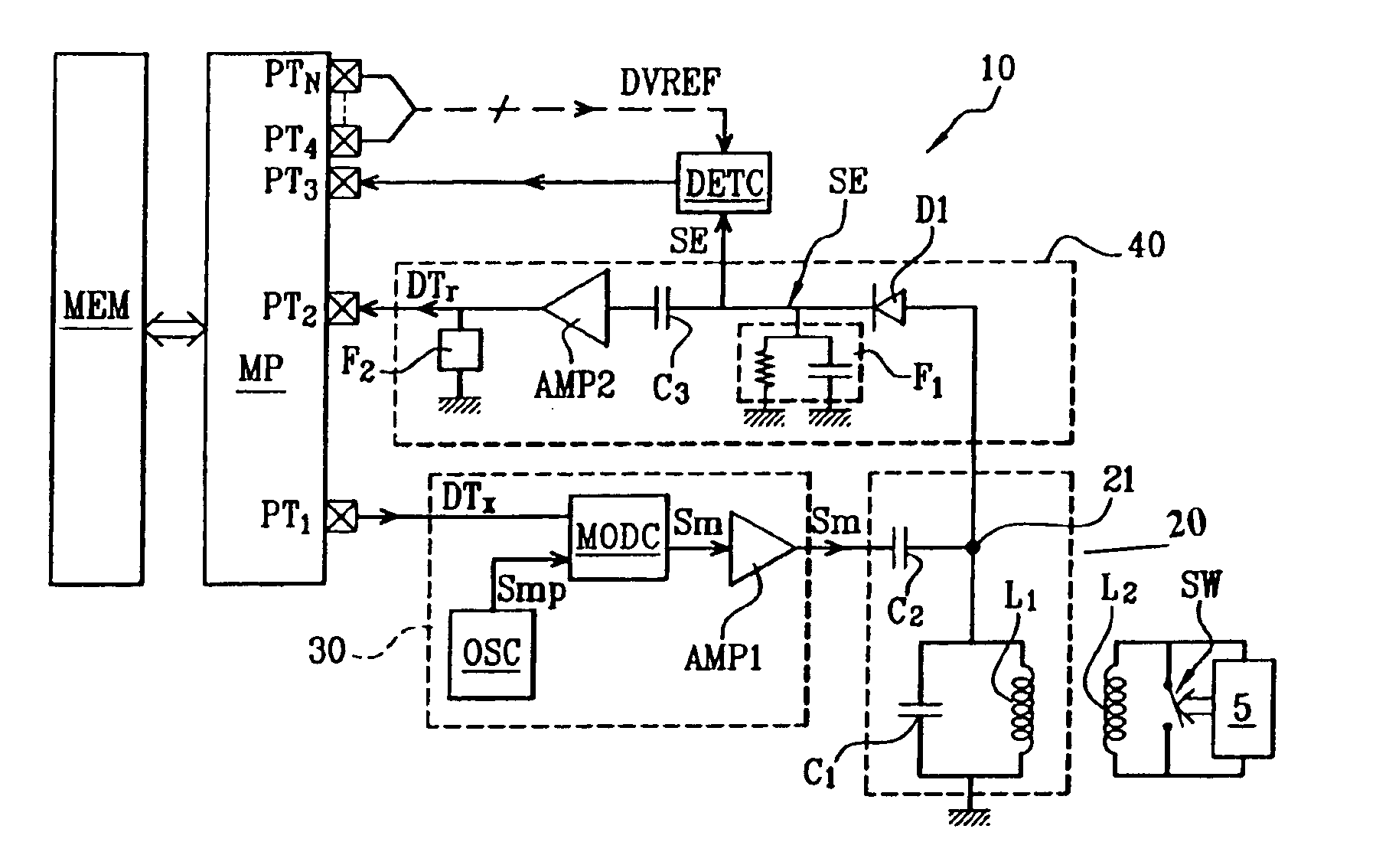
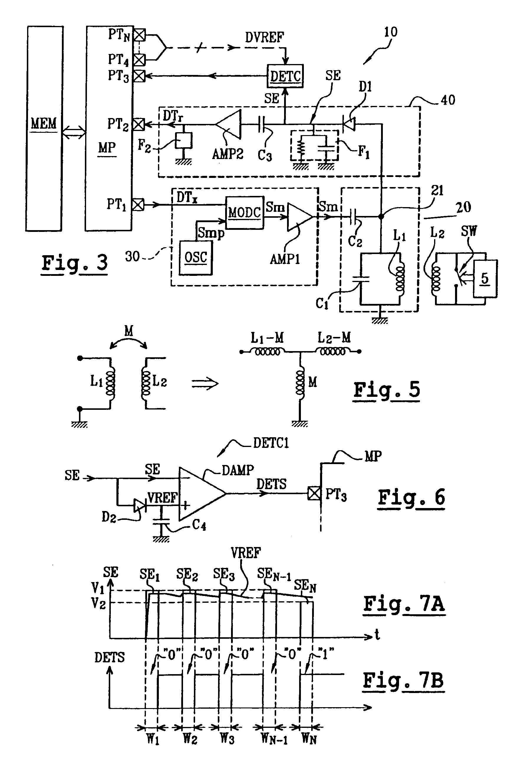
[0063]The method according to the present invention will be described below in relation with an example of classical contactless integrated circuit reader architecture, represented in FIG. 3 and described as an e.g. example, without limitation, of implementation of the present invention.

[0064]The reader 10 represented comprises a microprocessor MP, a program memory MEM, an antenna circuit 20, a data sending circuit 30 and a data receiving circuit 40.

[0065]The antenna circuit 20 is tuned to a determined resonance frequency, such as 13.56 megahertz (MHz) for example, and comprises an antenna coil L1 connected in parallel with a capacitor C1 to form a circuit L1C1. The circuit L1C1 has one terminal connected to a node 21 and the other terminal connected to the ground. The node 21 is connected to one end of a capacitor C2 the other end of which is connected to the output of the data sending circuit 30. The node 21 is also connected to the input of the data receiving circuit 40.

[0066]The...


PUM


Abstract

A contactless integrated circuit reader includes an antenna coil for emitting an oscillating magnetic field, and circuitry for detecting the presence of a contactless integrated circuit within a communication perimeter of the reader without receiving an identification message. The detection circuitry include circuitry for emitting short magnetic field pulses, circuitry for extracting from the antenna coil an envelope signal having envelope pulses corresponding to the magnetic field pulses, and circuitry for monitoring the amplitude of the envelope pulses, arranged for detecting a variation in the amplitude of the envelope pulses representative of the entry of the contactless integrated circuit into the communication perimeter of the reader.

Description

CROSS-REFERENCE TO RELATED APPLICATIONS[0001]This application is a continuation of International Application No. PCT / FR02 / 04361, filed Dec. 13, 2002, and the disclosure of which is incorporated herein by reference.BACKGROUND OF THE INVENTION[0002]The present invention relates to the field of data transmissions by inductive coupling. In particular, the present invention relates to contactless integrated circuit readers, used to exchange data with portable electronic objects comprising a contactless integrated circuit, such as contactless smart cards, contactless electronic tags, contactless electronic badges, and the like. More particularly, the present invention relates to a contactless integrated circuit reader comprising an antenna coil for emitting an oscillating magnetic field, and means for detecting the presence of a contactless integrated circuit within a communication perimeter of the reader without receiving an identification message. The present invention also relates to a...

Claims


Application Information

Patent Timeline
IPC IPC(8): G06K7/00
CPCG06K7/0008H04B5/0075G06K7/10128H04B5/0031Y02D30/70H04B5/24H04B5/72
Inventor CHARRAT, BRUNO
Owner VERIMATRIX INC
Learn More