
Optical waveguide plate of surface light emitting apparatus

a technology of surface light and waveguide, which is applied in waveguides, planar/plate-like light guides, instruments, etc., can solve problems such as the generation of bright lines, and achieve the effects of suppressing effectively and preventing the occurrence of bright lines

Inactive Publication Date: 2005-06-07
NICHIA CORP
View PDF8 Cites 10 Cited by
  • Summary
  • Abstract
  • Description
  • Claims
  • Application Information

AI Technical Summary

Benefits of technology

[0009]Thus, an object of the present invention is to provide an optical waveguide that can emit light of intensity uniformly distributed over the light emitting surface and that can suppress the occurrence of the bright line.
[0017]Thus the interval between the vertical lines of dots is made different in the adjacent band regions in the optical waveguides of the third surface light emitting apparatus, and therefore there is no vertical line extending over a long distance, and the occurrence of bright line can be prevented, similarly to the first surface light emitting apparatus.
[0020]Moreover, in the optical waveguides of the first through third surface light emitting apparatus of the present invention, it is preferable that the dot has a concave portion and a convex portion, which enable the dot to diffuse light more effectively.
[0022]As described above, in the optical waveguide of the surface light emitting apparatus according to the present invention, since the dots are arranged so as to form band regions each being defined as a region that has a constant density of distribution and no vertical line extends over a long distance across adjacent band regions, the occurrence of bright line can be prevented.
[0023]Also according to the present invention, the dots may be randomly distributed in such a proper density required to prevent the occurrence of bright lines, thereby to effectively prevent the occurrence of bright lines.
[0024]Therefore, the present invention can provide the optical waveguide that is capable of emitting light uniformly through the light emitting surface, and suppressing the occurrence of bright lines.

Problems solved by technology

With the light diffusion dot pattern of the prior art shown in FIG. 21, however, there has been the problem of a bright line generated due to the arrangement of the light diffusing dots.

Method used


Image

  • Optical waveguide plate of surface light emitting apparatus
  • Optical waveguide plate of surface light emitting apparatus
  • Optical waveguide plate of surface light emitting apparatus

Examples


first embodiment

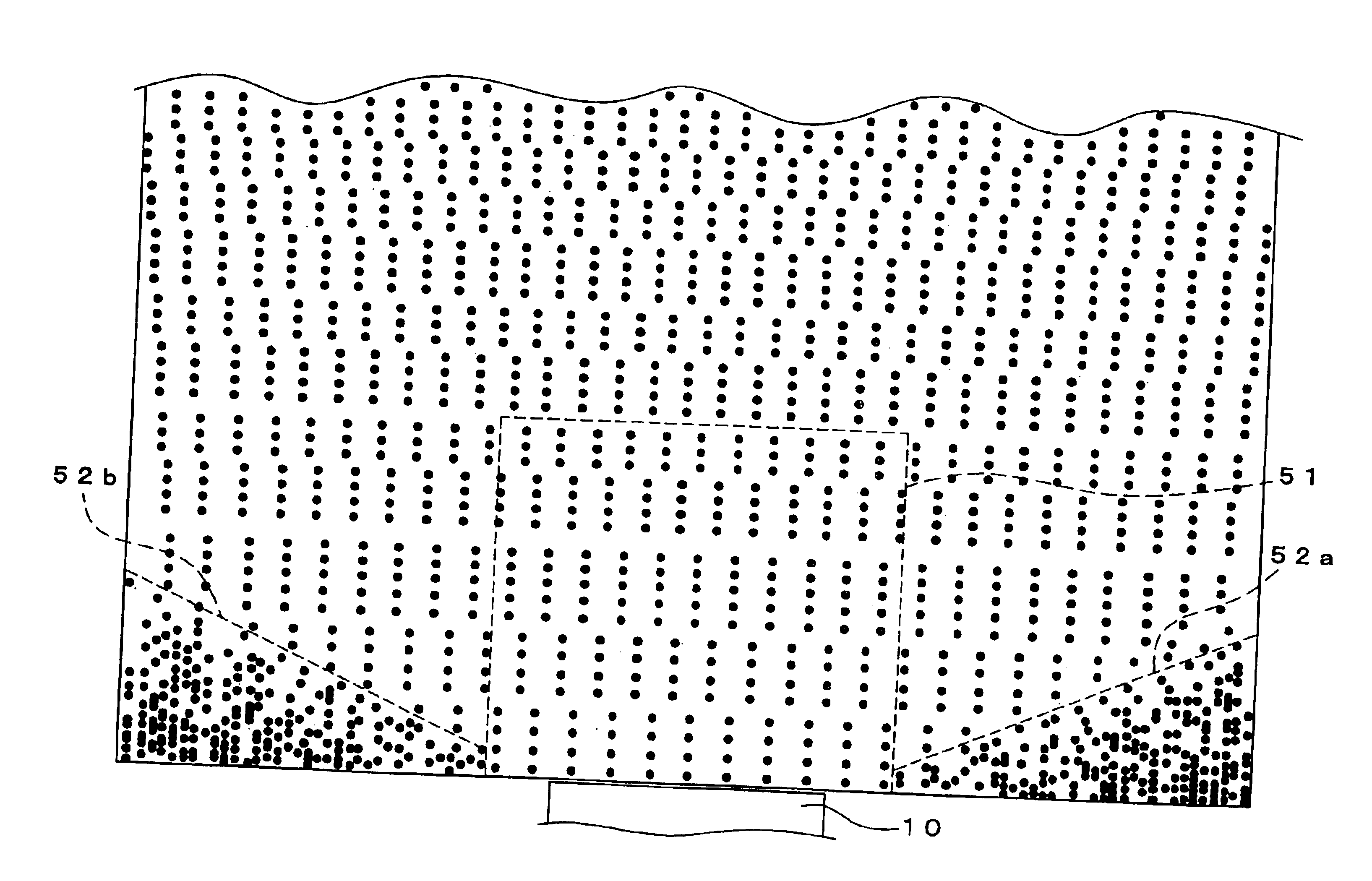
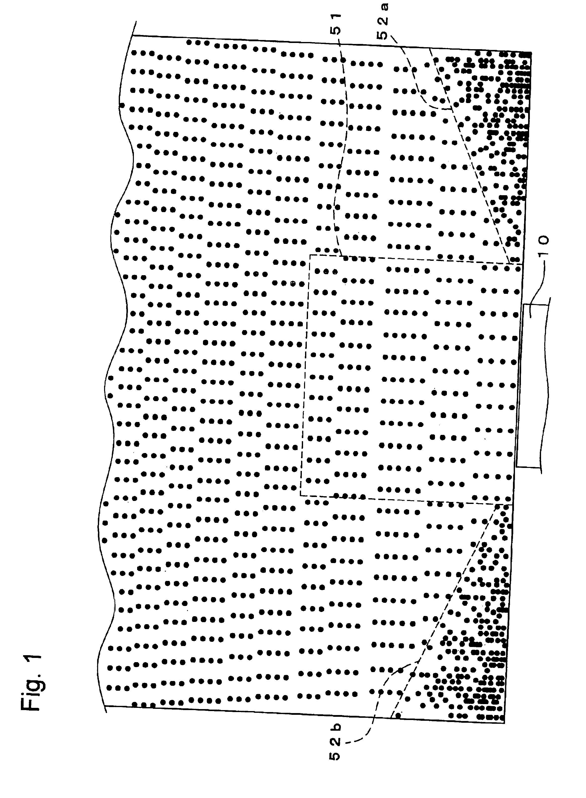
[0047]The first embodiment of the present invention provides an optical waveguide plate of a surface light emitting apparatus having such a constitution that light emitted by a light source is output with uniform intensity through a light emitting surface by forming a multitude of dots in a predetermined pattern on a reflecting surface that is a principal plane opposing another principal plane serving as the light emitting surface, wherein the dots are distributed in a pattern unique to the present application.

[0048]Specifically, the optical waveguide of the first embodiment has the dots formed as described below in major portions of the reflecting surface except for corners 52a, 52b located at both sides of the end face where a light source 10 is provided.

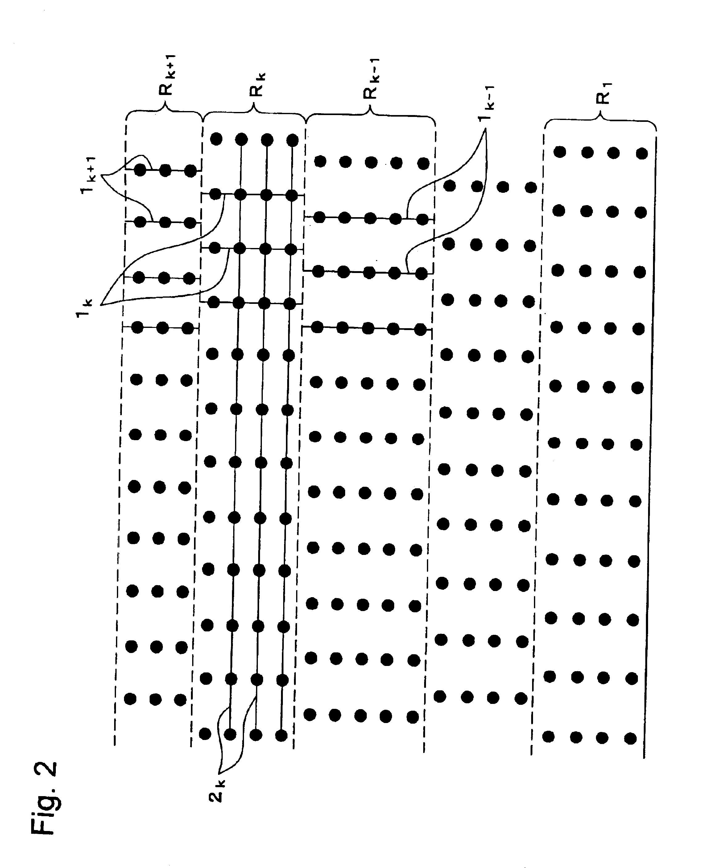
[0049]FIG. 1 is a plan view showing the distribution of the dots formed on the reflecting surface of the optical waveguide plate, and FIG. 2 is an enlarged view of a part (indicated by numeral 51) of FIG. 1.

(Band Region where Dots...

second embodiment

Variation of Second Embodiment

[0114]In the light diffusion pattern creating method of the second embodiment described above, circles representing the dots are placed in each cell in step S5 and redundant circles are randomly deleted from the circles of each cell in step S6, but the present invention is not limited to this procedure. Step S5 and step S6 may be replaced with the procedure described below.

[0115]Positions 22 for placing dots are determined in each cell so as to pace the maximum number of dots in each cell without any dots overlapping each other as shown in FIG. 10A.

[0116]The dots 21 having diameter of R are placed randomly by the required number determined in step S3 in each cell where the positions to place the dots have been determined, as shown in FIG. 10B.

[0117]This procedure also creates such a light diffusion dot pattern as the density of dots increases with the distance from the light source so as to compensate for the attenuation of light and the dots are random...


PUM


Abstract

An optical waveguide for emitting light of uniform intensity distributed over the light emitting surface so as to suppress the occurrences of bright lines includes an optical waveguide and surface light emitting apparatus that has a light emitting plane and a reflecting plane that oppose each other. The reflecting surface has a plurality of dots formed thereon so that light entering from the light source, provided on one end face or two opposing end faces, is output through the light emitting surface with uniform intensity, wherein the dots are arranged so as to form band regions each being defined as a region that has a constant density of distribution. A plurality of vertical lines of the dots are formed at substantially equal intervals in each of the band regions in the direction toward adjacent bands, and the interval between the vertical lines of dots is made different in different bands.

Description

BACKGROUND OF THE INVENTION[0001]1. Field of the Invention[0002]The present invention relates to an optical waveguide plate of a surface light emitting apparatus used for spreading light from a light source over the entire light emitting surface and emitting the light.[0003]2. Description of the Related Art[0004]Such surface light emitting apparatus have recently been used as the light source for backlight of a liquid crystal display, that outputs light from a point source such as LED chip by spreading the light over a plane. In the surface light emitting apparatus, light emitted by one or more light emitting diode enters through one end of an optical waveguide plate that has opposing principal planes, and exits through the whole area of the other principal plane of the waveguide.[0005]The surface light emitting apparatus has such a constitution as shown in a plan view of FIG. 20, comprising a casing 903, an optical waveguide plate 901 made of a transparent resin that has a first pr...

Claims


Application Information

Patent Timeline
IPC IPC(8): F21V8/00G02F1/1335G02B6/00
CPCG02B6/0036G02B6/0061Y10S385/901G02B6/0091G02F1/1335
Inventor TAMURA, YUUKIKUNIKATA, KOICHISHIOTA, NOBUTOSHINAKANISHI, EIJI
Owner NICHIA CORP
Learn More