
Method and apparatus for generating a density map using dual-energy CT

a density map and computed tomography technology, applied in the field of medical imaging, can solve the problems of inability to accurately perform bmd, time-consuming and wasteful computer resources, and the process of decomposing acquired data into the data associated with the basis materials,

Active Publication Date: 2005-06-07
GENERAL ELECTRIC CO
View PDF4 Cites 42 Cited by
  • Summary
  • Abstract
  • Description
  • Claims
  • Application Information

AI Technical Summary

Benefits of technology

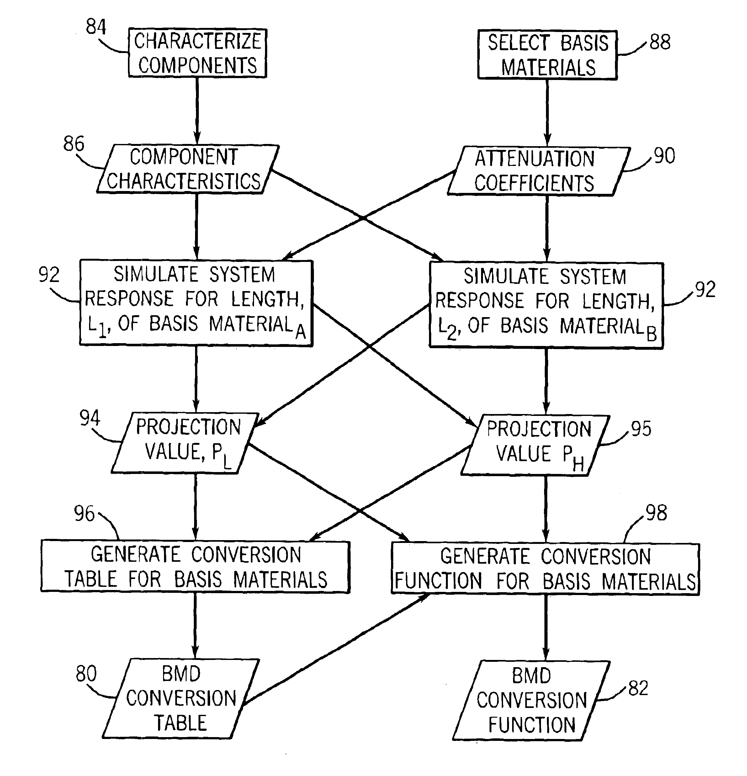
[0009]The present technique provides a novel approach for generating one or more density maps using a dual-energy CT system. For example, a basis material decomposition table or function may be generated by simulating the response of the CT system to various lengths of basis materials, taking into account the characteristics of the components of the system as well as the attenuation coefficient for the basis material. The characteristics of the components may include the X-ray spectra for a given peak kilovoltage and the detector response. The basis material decomposition table or function thus generated may be used to derive density line-integral projections determined from measured projection data. The density line-integral projections may in turn be reconstructed to generate a density map that is representative of the basis material. Series of density maps may be associated to form a volu

Problems solved by technology

The process of decomposing the acquired data into the data associated with the basis materials, i.e., the materials for which images are desired, may be complex.
The inversion process may be inadequate to account for realistic system response, particularly for complex detector configurations or imperfect detector characteristics, and thus may be unable to accurately perform BMD in some circumstances.
This solution, however, may be time-consuming and wasteful of computer resources.

Method used


Image

  • Method and apparatus for generating a density map using dual-energy CT
  • Method and apparatus for generating a density map using dual-energy CT
  • Method and apparatus for generating a density map using dual-energy CT

Examples


Embodiment Construction

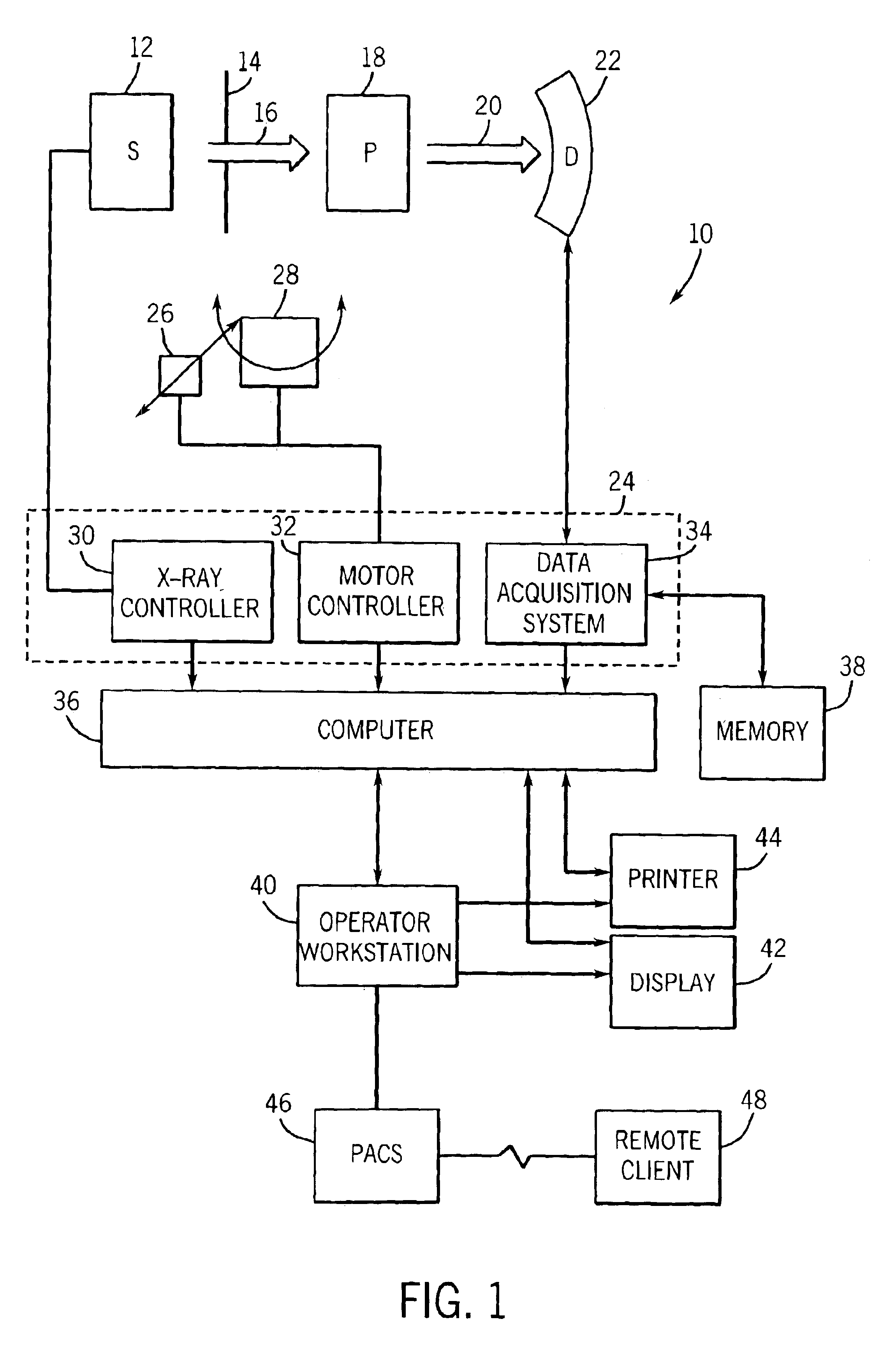
[0017]FIG. 1 illustrates diagrammatically an imaging system 10 for acquiring and processing image data. In the, illustrated embodiment, system 10 is a dual energy computed tomography (DE-CT) system designed to acquire image data at two or more X-ray energy levels or spectra and to process the image data for display and analysis in accordance with the present technique. Though the present discussion will be presented in the context of a DE-CT system, such as the one depicted, it should be understood that the present technique is equally applicable to dual-energy X-ray imaging in other contexts such as projection X-ray imaging or tomosynthesis. Alternately, the imaging system 10 may be designed to acquire image data at a single spectrum using a detector with energy resolution, which allows the energy level of each detected photon to be assessed. In the embodiment illustrated in FIG. 1, imaging system 10 includes a source of X-ray radiation 12 positioned adjacent to a collimator 14. In...


PUM


Abstract

The present technique provides for the generation of density maps using one or more basis material decomposition tables or functions. The basis material decomposition tables or functions are generated by simulating the system response to various lengths of basis materials using component characteristics of the CT system as well as the attenuation coefficient for the desired basis material. Measured projection data may be processed using the basis material decomposition tables or functions to provide a set of density line-integral projections that may be reconstructed to form a density map or image.

Description

CROSS-REFERENCE TO RELATED APPLICATIONS[0001]This application claims the benefit of U.S. Provisional Application No. 60 / 397,658 filed on Jul. 23, 2002 and U.S. Provisional Application 60 / 398,463 filed on Jul. 25, 2002.BACKGROUND OF THE INVENTION[0002]The present invention relates generally to the field of medical imaging. In particular, the following techniques relate to dual energy computed tomography imaging systems and basis material decomposition within such systems.[0003]Computed tomography (CT) imaging systems measure the intensity of X-ray beams passed through a patient from numerous angles. With sufficient angular coverage around the patient, cross-sectional images can be formed revealing the inner structure of the scanned object. The images are typically displayed on a cathode ray tube, and may be printed or reproduced on film. A virtual 3-D image may also be produced by a CT examination.[0004]CT scanners operate by projecting X-ray beams from an X-ray source through an att...

Claims


Application Information

Patent Timeline
IPC IPC(8): A61B6/03G01N23/04G01N23/02G06T5/00G06T11/00G06T5/50A61B6/00G06T7/20
CPCA61B6/032A61B6/405A61B6/4241A61B6/482A61B6/541G01N23/046G06T5/50G06T7/2033G06T11/005G06T5/003A61B6/4035G01N2223/612A61B6/503G06T2211/408G06T2211/412Y10S378/901G06T2207/10081G06T2207/30004G01N2223/419A61B6/563G06T7/246G06T5/73
Inventor WU, XIAOYELEBLANC, JAMESPFOH, ARMIN
Owner GENERAL ELECTRIC CO
Learn More