
Pulse controlled phase modulator

a phase modulator and pulse control technology, applied in the field of optical phase modulators, can solve the problems of not being as efficient as an optical pulse controlled phase modulator, not well suited to phase modulating one optical signal, and relatively slow devices

Inactive Publication Date: 2005-06-07
ROMANIUK CHARLES CHRISTOPHER
View PDF3 Cites 12 Cited by
  • Summary
  • Abstract
  • Description
  • Claims
  • Application Information

AI Technical Summary

Benefits of technology

"The patent describes a device called a pulse controlled phase modulator that can efficiently produce a phase-modulated output signal from a pulsed input signal. This is achieved by using a switch, such as a threshold device, to pulse modulate a dependent signal with the pulsed input signal. The resulting dependent signal is combined with an independent signal to produce the continuous wave output signal. The pulse controlled phase modulator is a simple device and can produce a more efficient output signal than previous methods."

Problems solved by technology

These devices are relatively slow and usually require a large electronic signal to produce a large phase shift.
These devices are not well suited for phase modulating one optical signal with another pulsed optical signal, and are not as efficient as an optical pulse controlled phase modulator.
However, this method does not phase modulate the input signal relative to a known phase value and, therefore, the phase of the signal is still not known after modulation.
However, the optical refractive index change is a relatively weak physical effect, usually requiring large modulating signals and materials with large nonlinear properties.
However, these devices are limited to signals with known relative phase values.
However, heterodyne and homodyne receivers require some electronic control and are more complex, less efficient, and slower than a pulse controlled phase modulator.

Method used


Image

  • Pulse controlled phase modulator
  • Pulse controlled phase modulator
  • Pulse controlled phase modulator

Examples


Embodiment Construction

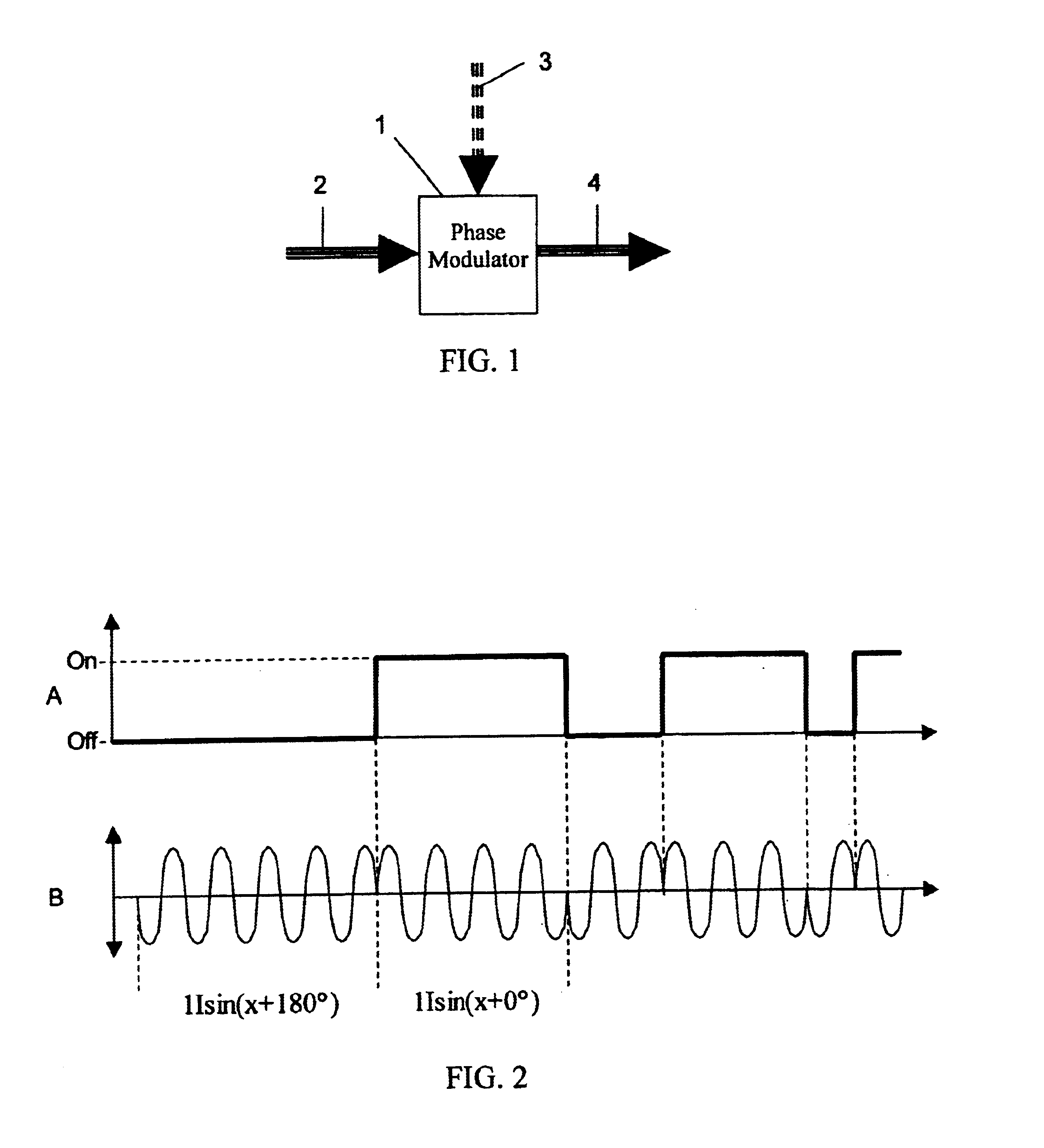
[0026]Referring to FIG. 1, a pulse controlled phase modulator 1 receives a continuous wave (CW) coherent input signal 2 and a pulsed input signal 3 and produces a continuous wave phase modulated output signal 4. As shown in FIG. 2, the output signal 4, resulting from the pulsed input signal 3, such as a signal A, is a constant magnitude binary phase shift keying (BPSK) signal, such as a signal B, with the same frequency as the CW input signal 2. For example, using the CW input signal 2 as 1I sin(x+0°), when the pulsed input signal 3 is ON, the output signal is 1I sin(x+0°), and when the pulsed input signal 3 is OFF, the output signal 4 is an inverted signal of 1I sin(x+180°) which is equal to −1I sin(x+0°).

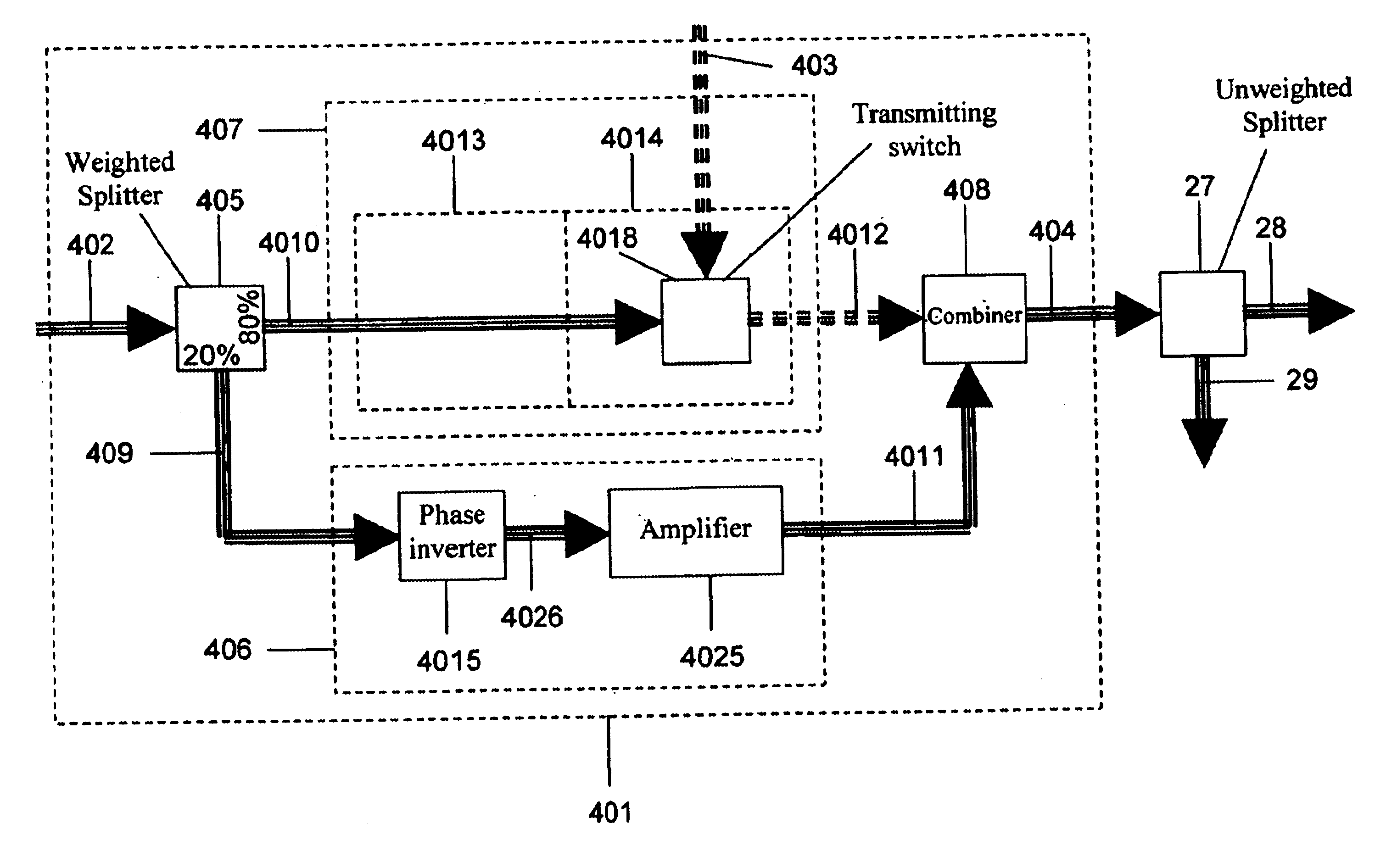
[0027]As shown in FIG. 3, the pulse controlled phase modulator 1 consists of a splitter 5, an independent stage 6, a dependent stage 7, and a combiner 8. The splitter 5 receives the continuous wave input signal 2 and divides it into two signals: an independent signal 9 and a depen...


PUM

PropertyMeasurementUnit
wavelengthaaaaaaaaaa
heightaaaaaaaaaa
heightaaaaaaaaaa

Abstract

A pulse controlled phase modulator device converts an unknown phase pulsed input signal to a continuous wave phase modulated output signal. The pulsed input signal activates a switch, such as a saturable absorber operating near saturation, to pulse modulate a dependent signal that has a known phase value. A combiner combines the dependent signal with an independent signal to produce the constant magnitude continuous wave phase modulated output signal. The output signal is a binary phase shift keying signal with the same frequency as the continuous wave input signal. An amplifier or weighted splitter is used to make the dependent signal larger in magnitude than the independent signal and a phase inverter is used to make the dependent and independent signals opposite in phase.The pulse controlled phase modulator consists of a splitter, an independent stage, a dependent stage, and a combiner. A threshold device is also used on the pulsed dependent signal to inhibit output magnitude variations.

Description

CROSS-REFERENCE TO RELATED APPLICATIONS[0001]Not ApplicableSTATEMENT REGARDING FEDERALLY SPONSORED RESEARCH OR DEVELOPMENT[0002]Not ApplicableREFERENCE TO A “MICROFICHE APPENDIX”[0003]Not ApplicableBACKGROUND OF THE INVENTION[0004]1. Field of the Invention[0005]The present invention relates generally to optical phase modulators and relates specifically to optical phase modulators controlled by a pulsed optical input signal.[0006]2. Discussion of Related Art[0007]Optical phase modulators are commonly used devices and are well known in the art. They are useful for converting an electrical, acoustical, or optical signal to an optical signal with a specific phase value. Optical phase modulators have also been developed as optical devices for logic gates and signal receivers. A variety of optical phase modulators are used to provide digital binary phase shift keying (BPSK) modulated signals. However, a more efficient and faster phase modulator which can receive a pulsed input signal of u...

Claims


Application Information

Patent Timeline
Patent Type & Authority Patents(United States)
IPC IPC(8): G02F1/35H01S5/50H01S5/00H01S5/10H01S5/062
CPCG02F1/3515G02F1/3523G02F2203/50H01S5/50H01S5/06246H01S5/1071H01S5/06223
Inventor ROMANIUK, CHARLES CHRISTOPHER
Owner ROMANIUK CHARLES CHRISTOPHER
Learn More