
Voltage controlled oscillator

a voltage control and oscillator technology, applied in the direction of automatic control, instruments, measurement devices, etc., can solve the problems of limiting the accuracy that can be achieved in centering the frequency band, adding additional cost, and using additional valuable real estate, so as to achieve the effect of minimal tuning range, minimum tuning range, and easy adjustmen

Inactive Publication Date: 2005-06-07
TAMIRAS PER PTE LTD LLC
View PDF21 Cites 74 Cited by
  • Summary
  • Abstract
  • Description
  • Claims
  • Application Information

AI Technical Summary

Benefits of technology

[0013]Embodiments of the present invention are advantageous in that a voltage controlled oscillator having a minimum tuning range can be utilized. A minimal tuning range is advantageous in that the voltage controlled oscillator is less sensitive to noise and interference. Embodiments of the present invention are also advantageous in that process variations in the voltage controlled oscillator may be readily compensated for. Embodiments of the present invention are also advantageous in that variations in the operating temperature of the voltage controlled oscillator circuit may be readily compensated for. Embodiment of the present invention are also advantageous in that minimal manual tuning is required.

Problems solved by technology

However, process variations limit the accuracy that can be achieved in centering the frequency band around the desired frequency.
This method is disadvantageous in that it adds additional cost and uses additional valuable real estate.
The additional tuning range is also disadvantageous in that it causes the voltage controlled oscillator 125 to be more sensitive to noise and interference.
However, manual adjustments are an added cost, and require the customer or user to correctly perform the operation.
This can lead to performance degradation and can be tedious and / or error prone.

Method used


Image

  • Voltage controlled oscillator
  • Voltage controlled oscillator
  • Voltage controlled oscillator

Examples


Embodiment Construction

[0021]Reference will now be made in detail to the embodiments of the invention, examples of which are illustrated in the accompanying drawings. While the invention will be described in conjunction with the preferred embodiments, it will be understood that they are not intended to limit the invention to these embodiments. On the contrary, the invention is intended to cover alternatives, modifications and equivalents, which may be included within the spirit and scope of the invention as defined by the appended claims. Furthermore, in the following detailed description of the present invention, numerous specific details are set forth in order to provide a thorough understanding of the present invention. However, it will be obvious to one of ordinary skill in the art that the present invention may be practiced without these specific details. In other instances, well-known methods, procedures, components, and circuits have not been described in detail as not to unnecessarily obscure aspe...


PUM


Abstract

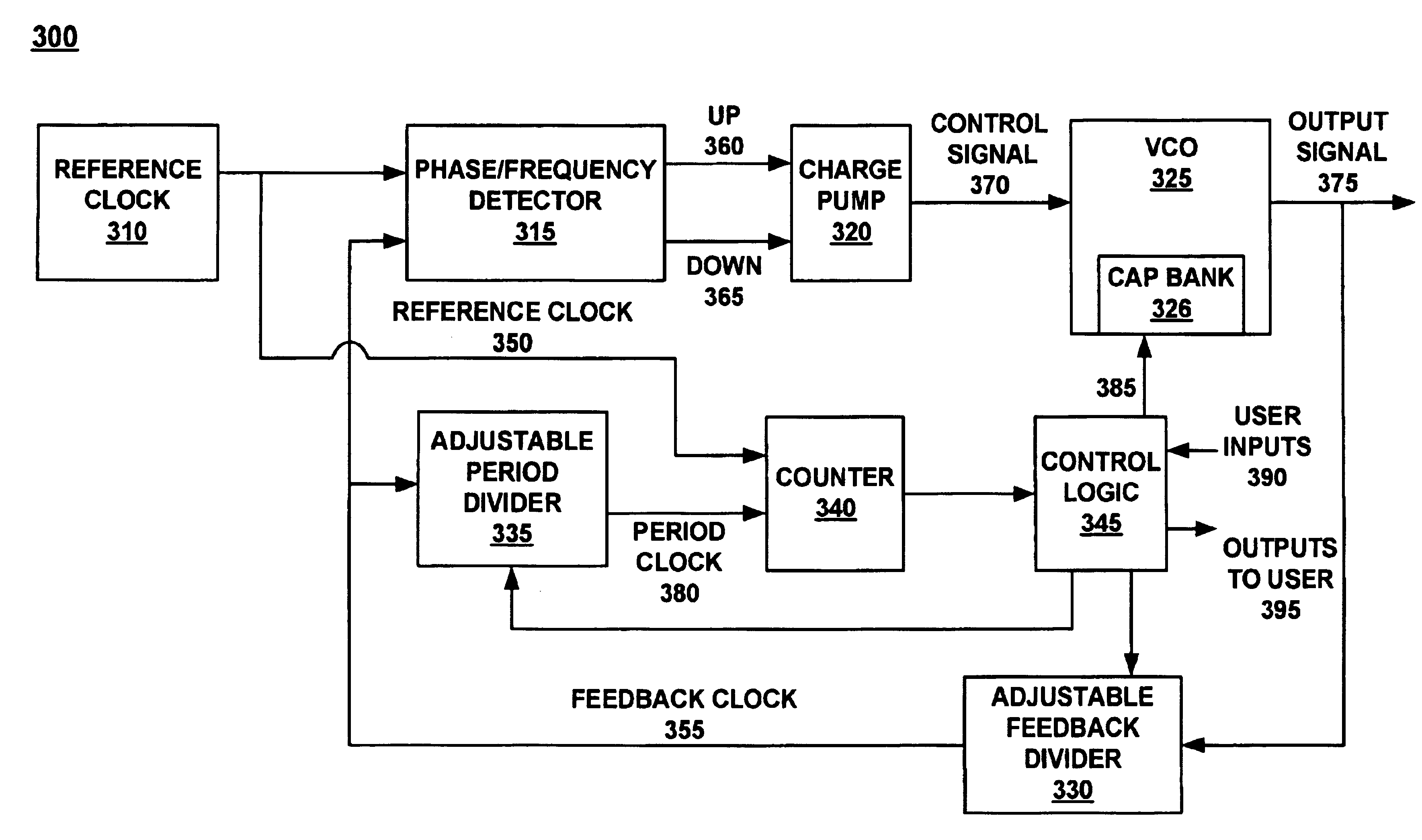
Embodiments of the present invention provide a method of centering an operating band of a voltage controlled oscillator around a desired operating frequency. In one embodiment, an adjustable feedback divider provides for driving an output signal to the top and bottom of the operating band. An adjustable period divider and counter provide a plurality of count values for use in determining a mid-point of the operating band. A capacitance bank provides for selectively adjusting a capacitance of the voltage controlled oscillator, thereby adjusting the operating band.

Description

FIELD OF THE INVENTION[0001]Embodiments of the present invention relate to voltage control oscillators (VCO) circuits, and more particularly to centering the operating band of a VCO circuit about a desired frequency.BACKGROUND OF THE INVENTION[0002]Voltage controlled oscillators (VCOs) are commonly employed in a variety of applications, including communication and timing circuitry. In particular, voltage controlled oscillators are commonly used in phase locked loop control systems. Functionally, a voltage controlled oscillator may be viewed as a circuit that seeks to transform an input control voltage signal to an output signal having a desired frequency.[0003]Referring to FIG. 1, a clock diagram of a phase lock loop voltage controlled oscillator (PLL VCO) 100 in accordance with the conventional art is shown. As depicted in FIG. 1, the PLL VCO 100 comprises a reference clock 110, a phase / frequency detector 115, a charge pump 120, a voltage controlled oscillator (VCO) 125, and a feed...

Claims


Application Information

Patent Timeline
IPC IPC(8): H03L7/087H03L7/08H03L7/099H03L7/113
CPCH03L7/113H03L7/099
Inventor MITCHELL, ERIC P.GEHRING, MARK R.
Owner TAMIRAS PER PTE LTD LLC
Learn More