
Recoil starter for backpack type power working machine

Inactive Publication Date: 2005-06-07
KIORITZ
View PDF15 Cites 7 Cited by
  • Summary
  • Abstract
  • Description
  • Claims
  • Application Information

AI Technical Summary

Benefits of technology

[0011]The present invention has been made in view of overcoming the aforementioned problems accompanied with the conventional recoil starters, and therefore, it is an object of the present invention to provide a recoil starter for a backpack type power working machine, which is capable of easily performing the starting operation of an internal combustion engine under the condition where the working machine is kept shouldered by the operator's back, which can be manufactured lighter in weight and lower in manufacturing cost as compared with a D.C. motor type recoil starter, and the recoil handle of which is substantially free from hindering the movement of the operator and can be easily grasped by fingers, thereby enabling the recoil handle to be easily pulled out.
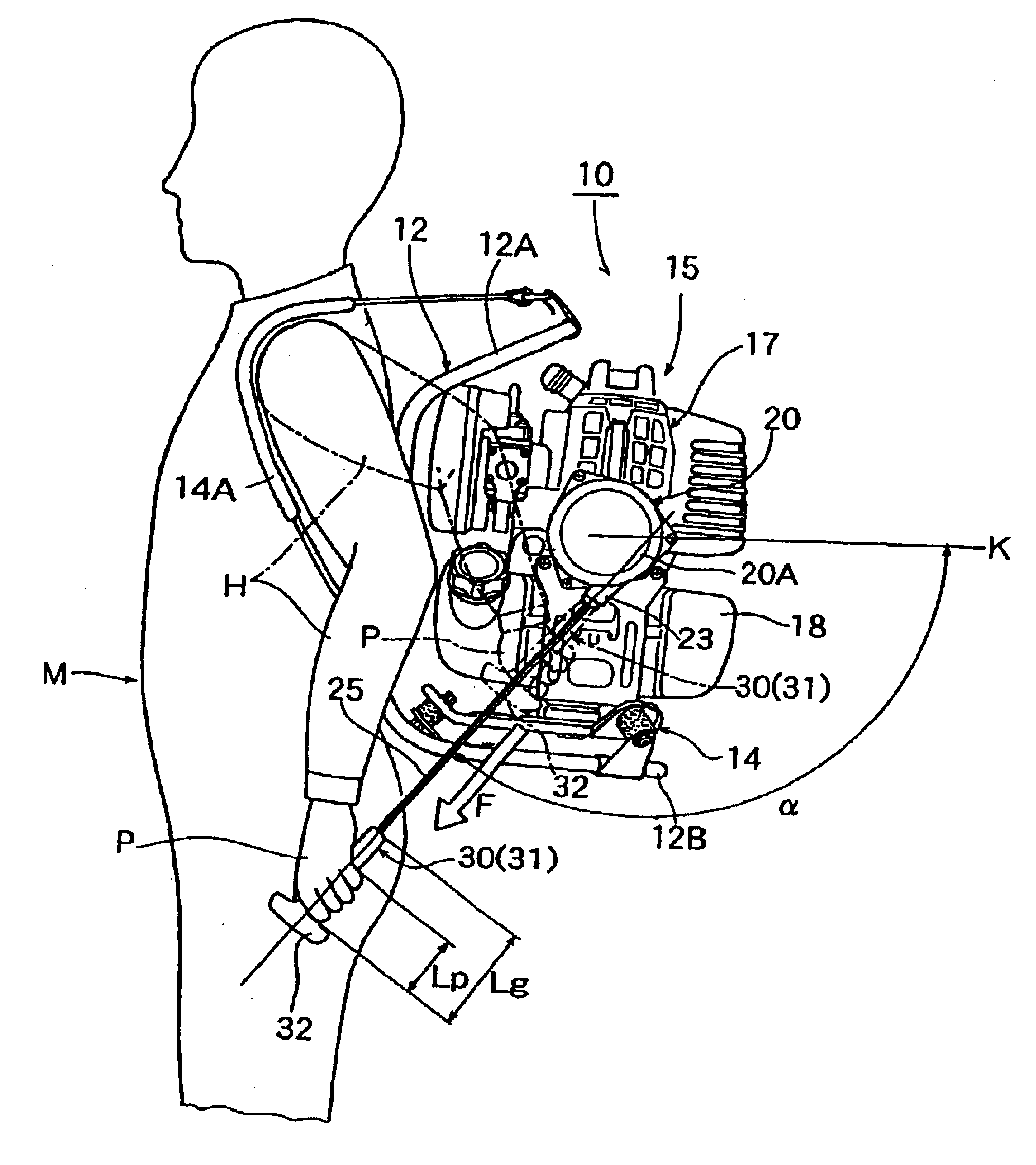
[0017]In a preferable embodiment of the recoil starter of the backpack type power working machine according to the present invention which is constructed as described above, since the recoil handle is disposed so as to be pulled down obliquely forward at an angle of 100° to 150° to the horizontal plane, the starting operation of the recoil starter can be easily performed with the working machine being kept shouldered by the operator's back. Moreover, according to the present invention, since only the mounting posture of the recoil starter and the recoil handle thereof are required to be modified with the main body of the recoil starter for a backpack type power working machine being permitted to be the same as the conventional recoil starter, it is possible to make the recoil starter lighter in weight and lower in manufacturing cost as compared with the D.C. motor type recoil starter. Further, since the recoil handle is positioned on the back of the operator, it is possible to prevent the recoil handle from hindering the movement of the operator during the operation of the power working machine.
[0018]Moreover, since the recoil handle is formed into a T-shaped configuration in side view, which comprises the grip portion having a length larger than the width of the palm of the operator's hand and a laterally extended stopper portion which is formed on a distal end, as viewed in the pullout direction, of the grip portion, it is possible to entirely grasp the recoil handle and to manipulate the recoil handle without imposing so much load on the grasping fingers as compared with the conventional clutch type recoil handle, thereby making it possible to easily perform the pulling operation of the recoil handle.
[0019]Further, since the recoil handle is made longer as compared with the conventional recoil handle, it is possible for an operator to easily reach the position of the recoil handle while shouldering the power working machine on his back. Additionally, since a laterally extended stopper portion is formed on the grip portion, it becomes possible to prevent the operator's hand from slipping out of the recoil handle, thereby enabling the pullout operation of the recoil handle (starting manipulation of the engine) and making it possible to minimize the failure of the starting manipulation of the engine.
[0022]According to this power-accumulating type recoil starter, since the buffering / power-accumulating means (a spiral spring mechanism) is interposed between the driving member and the driven member, it is possible to derive a buffering effect from the spiral spring mechanism during the first-half driving process (until the piston of the internal combustion engine reaches the top dead center thereof) in the pulling operation of the recoil rope (recoiling operation), to enable the pulling force of the recoil rope to be accumulated in the spiral spring mechanism. During the latter-half driving process, the pulling force thus accumulated in the spiral spring mechanism during the first-half driving process is permitted to be combined with the pulling force to be actually effected in the latter-half pulling operation of the recoil rope to thereby generate a resultant force, which is utilized as a force for starting the internal combustion engine. As a result, it is possible to minimize a fluctuation in pulling force of rope so as to smooth the rope-pulling operation, and also to enable the engine to be easily started without necessitating a large magnitude of pulling force.

Problems solved by technology

Therefore, it is difficult for the operator to reach the recoil handle under the condition where the working machine is kept shouldered by the operator's back, i.e. it is difficult for the operator to pull the recoil handle for starting the internal combustion engine under such a condition as mentioned above.
Therefore, if the operator wishes to restart the internal combustion engine after the engine is stopped while carrying the working machine on his back, the working machine is required to be dismounted from his back, causing significant inconvenience to the operator.
In that case however, the total weight of the working machine would be considerably increased due to the D.C. motor and the battery to be used as a power source for the D.C. motor, and the structure of the starter would become complicated, thus increasing the manufacturing cost thereof.
Since this recoil starter is constructed such that the recoil handle thereof (recoil rope and one end of the guide pipe) is not supported at all, it is difficult to smoothly perform the rope-pulling operation.
Moreover, since the recoil rope and the guide pipe end are allowed to hang around during the working operation, they may disturb the working operation, thus raising a problem.
However, there are problems that the face of the operator may be impinged against the recoil handle, thus hindering the movement of the operator, and that the recoil rope-pulling operation may become difficult.
Additionally, in the case of the conventional recoil starter according to the prior art, since the recoil handle is formed into such a configuration as to enable the recoil handle to be entirely grasped by fingers (i.e. clutch type configuration) in view of the attaching position and the pull-out direction of the recoil handle, it is unavoidable to cause a large magnitude of load to be imposed on the fingers on the occasion of pulling the recoil handle, and moreover, such a configuration is not necessarily convenient to grasp.

Method used


Image

  • Recoil starter for backpack type power working machine
  • Recoil starter for backpack type power working machine
  • Recoil starter for backpack type power working machine

Examples


Embodiment Construction

[0026]Next, one embodiment of the recoil starter according to the present invention will be explained with reference to the drawings.

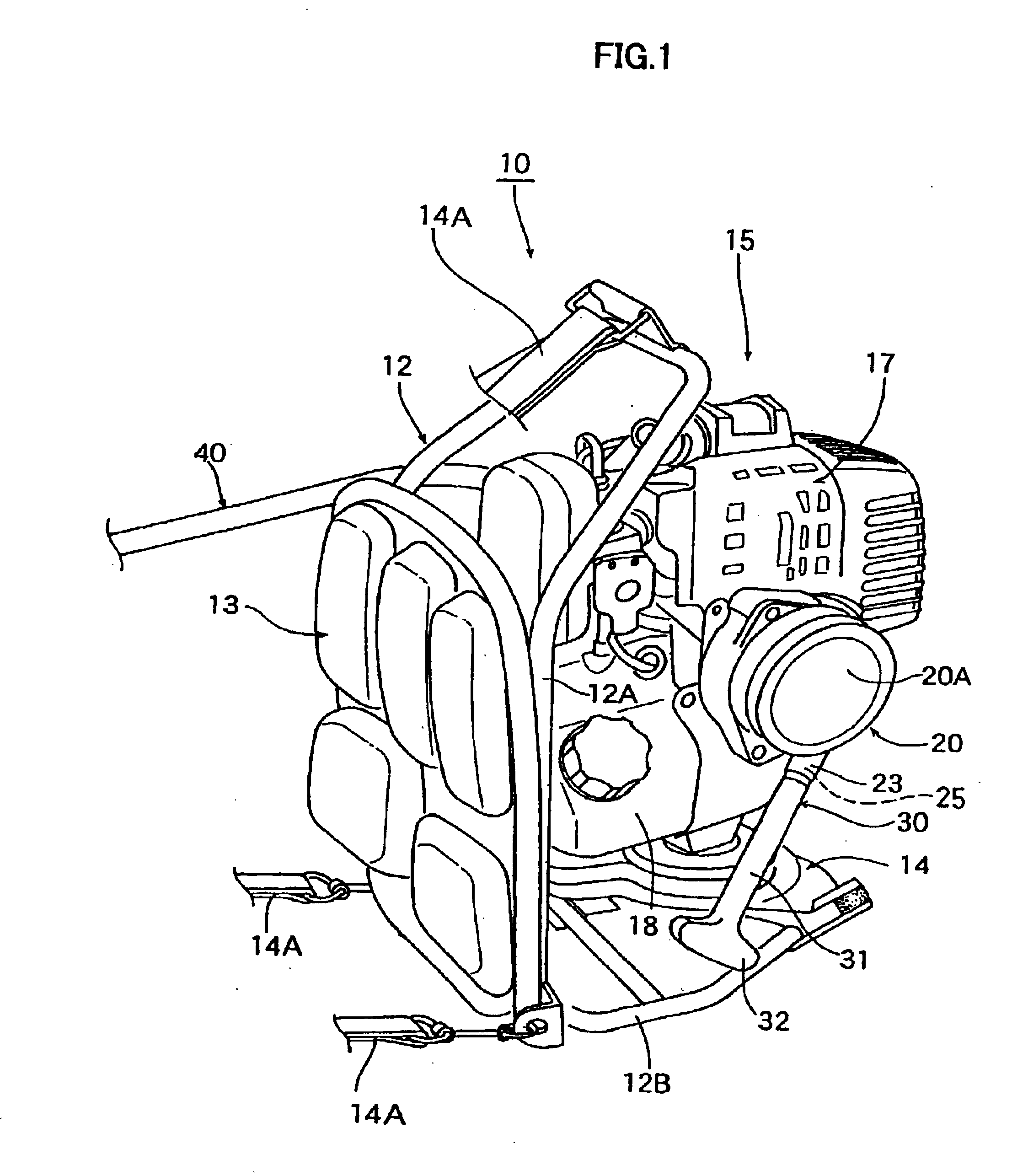
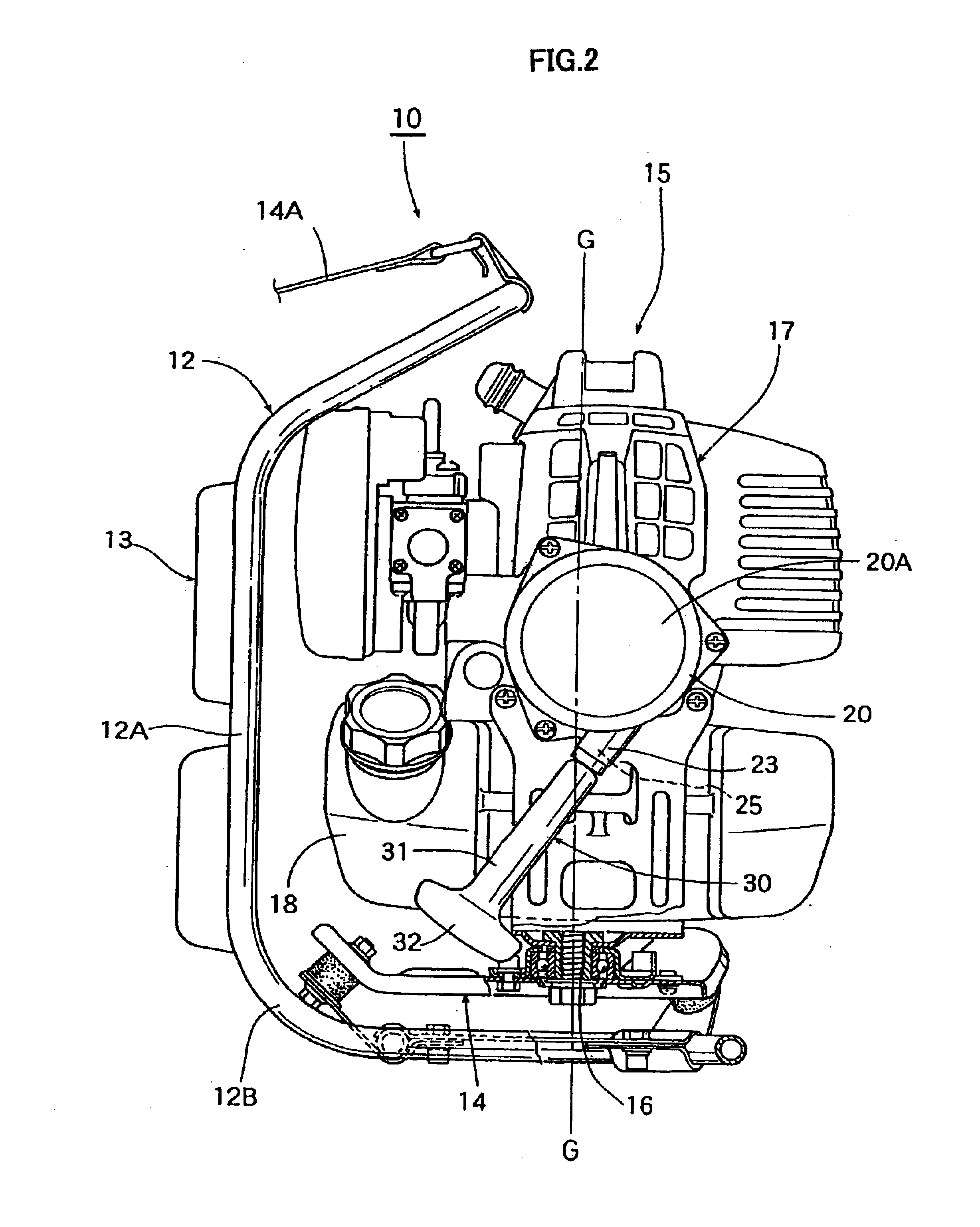
[0027]FIG. 1 is a perspective view of a recoil starter representing one embodiment of the present invention, which is shown together with a backpack type power brush cutter as one example of a backpack type power working machine as they are viewed from the left front side thereof, and FIG. 2 is a left side view of the backpack type power brush cutter including the recoil starter both shown in FIG. 1.

[0028]Referring to FIGS. 1 and 2, this backpack type power brush cutter 10 comprises an L-shaped (in side view) backpack frame 12 having a pair of shouldering bands 14A, a back-resting pad 13 secured to the vertical frame portions 12A of the shouldering frame 12, and a driving power source portion 15 mounted, through a mounting member 14 acting also as a vibration damping and absorbing member, on the bottom frame portions 12B of the backpack frame 12, this ...


PUM


Abstract

A recoil starter for a backpack type power working machine, which is capable of easily performing the starting operation of an internal combustion engine with the working machine being carried on the operator's back. In this recoil starter, the recoil rope and the recoil handle are disposed so as to be pulled down obliquely forward at an angle of 100° to 150° to the horizontal plane. The recoil handle is formed into a T-shaped configuration in side view, which comprises the grip portion and a laterally extended stopper portion which is formed on a distal end of the grip portion.

Description

BACKGROUND OF THE INVENTION[0001]1. Field of the Invention[0002]The present invention relates to a recoil starter for an internal combustion engine, and in particular, to a recoil starter to be employed for starting an internal combustion engine which is adapted to be mounted on a backpack type power working machine such as a backpack type power brush cutter, a backpack type power sprayer, etc.[0003]2. Description of the Related Art[0004]The recoil starter to be employed for starting an internal combustion engine such as air-cooled two-stroke gasoline engine which is adapted to be mounted on a backpack type power working machine is generally constructed such that it is provided with a recoil handle (recoil rope) so that the internal combustion engine can be started by pulling the recoil handle against the compression-resisting force of the engine, and that once this recoil handle is released, the recoil rope is automatically wound up to the original state thereof by the effect of re...

Claims


Application Information

Patent Timeline
IPC IPC(8): F02N3/02F02B63/02F02N3/00F02B63/00F02B75/02A01G3/08A01D34/67A01D34/68A01G23/00A01M7/00
CPCF02B63/02F02N3/02F02B2075/025
Inventor MATSUBAYASHI, TATSUHIKOKIKUCHI, SATORU
Owner KIORITZ
Learn More