
Adaptive antenna array wireless data access point

Inactive Publication Date: 2005-05-31
F POSZAT HU
View PDF14 Cites 71 Cited by
  • Summary
  • Abstract
  • Description
  • Claims
  • Application Information

AI Technical Summary

Benefits of technology

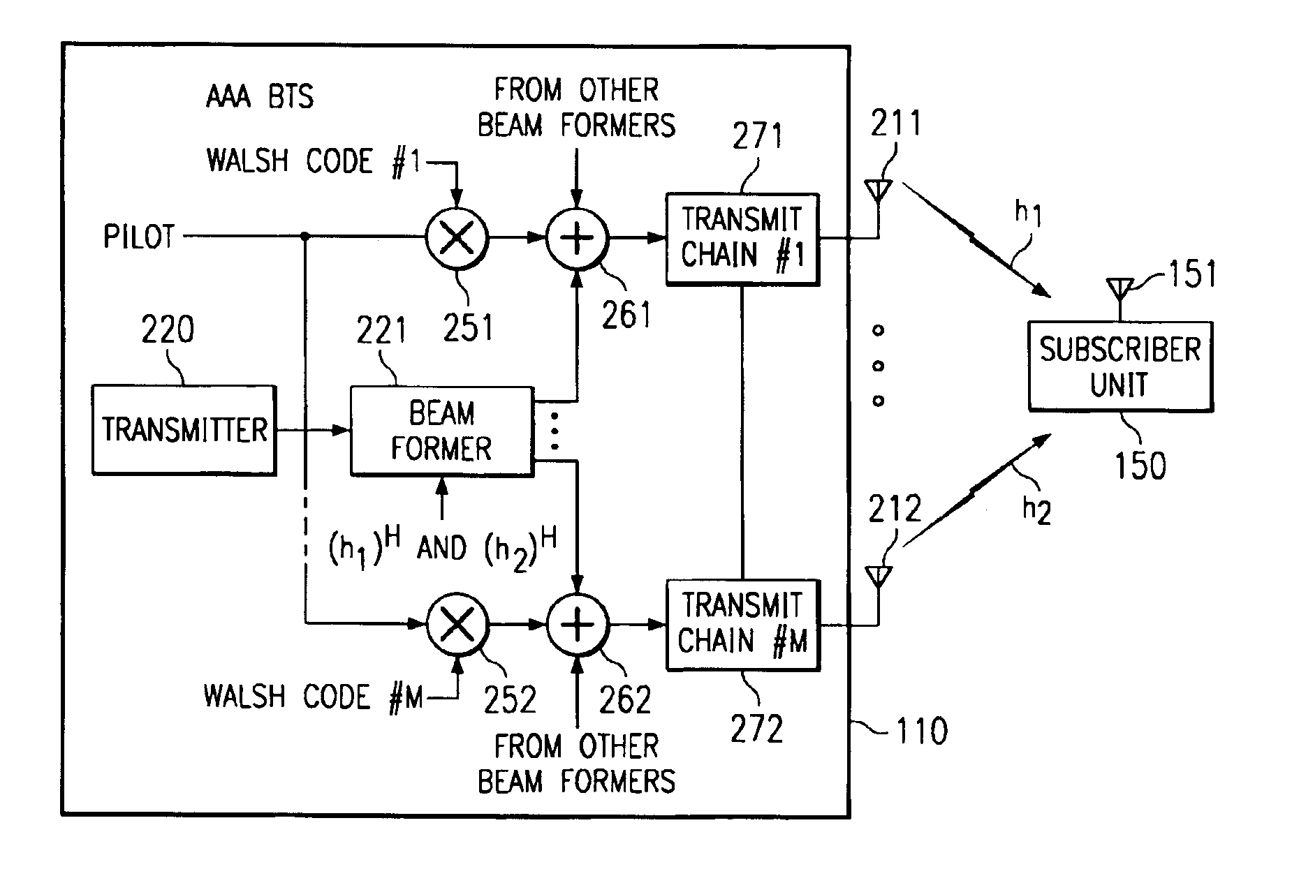
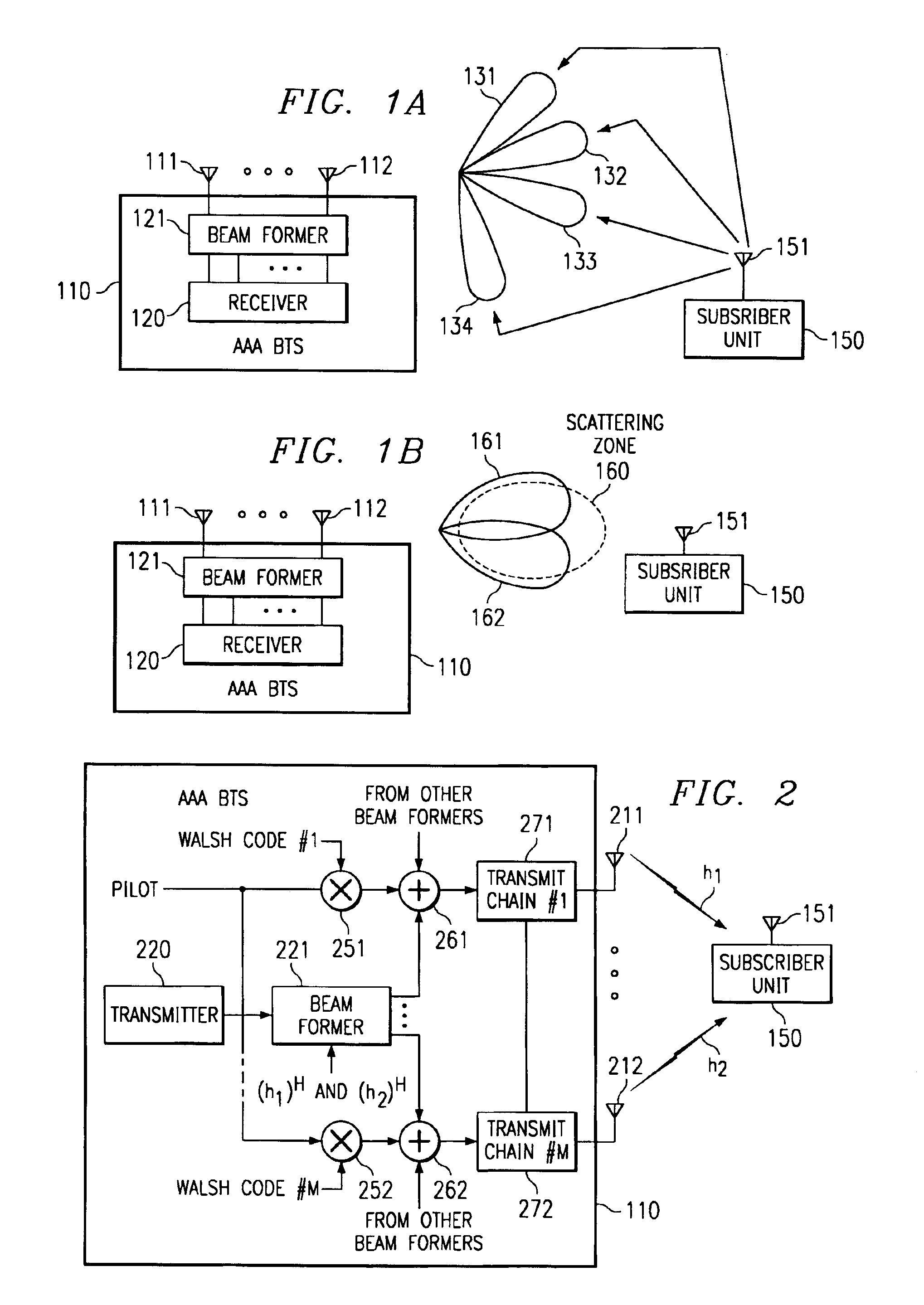
[0015]Various communication systems which may be adapted according to the present invention may implement a protocol which is not symmetrical. For example, an uplink frequency may be utilized which is different than a downlink frequency, such as in IS-95 cellular communications where the uplink and downlink frequencies differ by 60 MHZ or more. This difference in frequencies generally cause the uplink and downlink channels to be non-correlated. Accordingly, the angle of arrival and / or the time of arrival of the uplink and downlink channels, although statistically similar, may differ significantly. Accordingly, the use of downlink pilot signals according to the present invention in estimating a downlink channel and forming a downlink antenna beam assures that the channel estimation does not suffer from the effects of non-correlation of the uplink and downlink channels.
[0020]It is expected that as mobile data services become more ubiquitous, the future of such services depends on the ability of service providers to offer low cost subscription plans which, in a highly competitive market, can only be practically achieved through optimizing available capacity among a large number of subscribers. It is therefore believed that mobile data services are an excellent candidate for the adaptive array technology of the present invention. Embedding this technology into service providers' infrastructure could provide vary significant capacity increases through the ability to eliminate same cell interference for simultaneously served subscribers, reduction of inter-cell interference, and increasing signal to noise ratio of the intended subscriber and hence increase the user data rate, resulting in either higher throughout, the ability to support many more subscribers for a given infrastructure, or some combination thereof.

Problems solved by technology

Accordingly, there is often limited wireless spectrum availability for any particular service provider and / or any particular subscriber.
Information communication in such wireless communication systems is limited by various factors.
For example, cellular system capacity is almost always limited by inter and intra cell interference.
Accordingly, it can be appreciated that a simple increase in transmission power will often be insufficient to increase system capacity.
In some predominately data communication systems forward link (or downlink) bandwidth substantially limits capacity.
Accordingly, in such systems the forward link may present a bottleneck.
However, because data delivery is typically less time critical than voice data, the latency (sometimes on the order of several seconds) of this solution is often acceptable, although undesired.

Method used


Image

  • Adaptive antenna array wireless data access point
  • Adaptive antenna array wireless data access point
  • Adaptive antenna array wireless data access point

Examples


Embodiment Construction

[0030]In providing wireless communications, focusing energy in the direction of a receiving system, such as a subscriber unit in a cellular system, typically reduces the amount of power needed in order to maintain a given service quality. Accordingly, the use of relatively narrow antenna beams to focus energy in wireless communications both operates to increase signal quality at an intended receiver unit as well as to limit interfering energy experienced at an unintended receiver unit.

[0031]An array of antenna elements may be utilized to focus power received from a subscriber unit to the base station receiver (reverse or up link) and power transmitted to a subscriber unit by the base station transmitter (forward or down link). For example, phased arrays having circuitry coupled thereto to provide adaptive signal processing, e.g., adaptive beam forming, may be utilized to provide relatively narrow antenna beams focusing energy of signals communicated between a base station and an ass...


PUM


Abstract

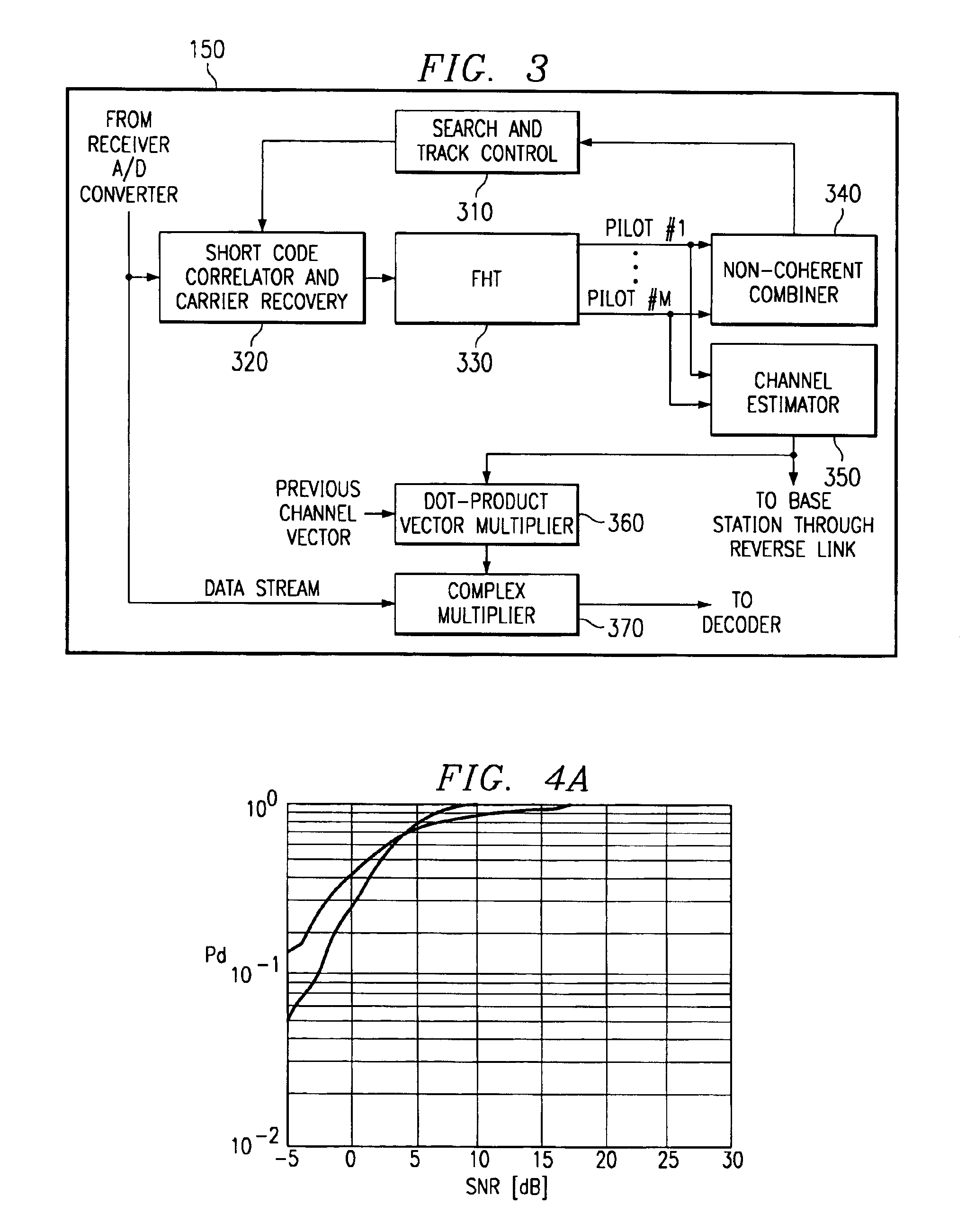
The invention provides systems and methods for providing improved wireless data communication. Preferred embodiments of the present invention utilize multiple antenna beams in the forward link to provide increased forward link capacity and / or improved forward link signal quality. Multiple orthogonal sub-pilots are transmitted from a plurality of antenna elements for use in determining forward link channel characteristics according to a preferred embodiment. Forward link channel estimates may then be made by the preferred embodiment subscriber units and provided in a reverse link control channel to the corresponding base station. Multiple beams may also be utilized in the reverse link to provide increased reverse link capacity, such as for use in providing feedback of forward link channel estimates.

Description

RELATED APPLICATIONS[0001]The present application is related to co-pending U.S. provisional patent application Ser. No. 60 / 168,367 entitled “Adaptive Antenna Array Wireless Data Access Point,” filed Dec. 1, 1999, to which the benefit of priority of filing is hereby claimed and the disclosure of which is hereby incorporated herein by reference.[0002]The present application is also related to co-pending and commonly assigned U.S. patent application Ser. No. 09 / 310,567 entitled “Manifold Assisted Channel Estimation and Demodulation for CDMA Systems in Fast Fading Environments,” filed May 12, 1999, U.S. patent application Ser. No. 09 / 511,665 entitled “Transmitting Beam Forming in Smart Antenna Array Systems”, filed Feb. 23, 2000, U.S. patent application Ser. No. 09 / 672,175, “Methods of Phase Recovery in Cellular Communication Systems”, and U.S. patent application Ser. No. 09 / 229,482 entitled “Practical Space-Time Radio Method for CDMA Communication Capacity Enhancement,” filed Jan. 13, ...

Claims


Application Information

Patent Timeline
IPC IPC(8): H04B7/04H04B7/06H04B7/08
CPCH04B7/086H04B7/0684H04B7/0619H04B7/0617
Inventor SCHERZER, SHIMON B.WONG, PIU BILL
Owner F POSZAT HU
Learn More