
Phase noise compensation in an interferometric system

a phase noise compensation and interferometer technology, applied in the field of measurement, can solve problems such as phase noise effects, and achieve the effect of limiting the precision of measurement procedures and reliable determination of optical characteristics of duts

Inactive Publication Date: 2005-05-31
AGILENT TECH INC
View PDF17 Cites 14 Cited by
  • Summary
  • Abstract
  • Description
  • Claims
  • Application Information

AI Technical Summary

Benefits of technology

The invention is about a method to reduce the effects of phase noise in an interferometric system. This is achieved by using a reference interferometer to measure the phase noise. The method can be used to eliminate the adverse effects of phase noise in a test interferometer or in other components of the system. The method involves measuring the differences between the phase at the output of each interferometer at different times. By canceling out the phase noise effects, the method allows for more reliable determinations of the optical characteristics of a device under test. The invention allows for high-delay devices to be analyzed and reduces the impact of phase noise on measurement precision.

Problems solved by technology

These random fluctuations produce the phase noise effects.

Method used


Image

  • Phase noise compensation in an interferometric system
  • Phase noise compensation in an interferometric system
  • Phase noise compensation in an interferometric system

Examples


Embodiment Construction

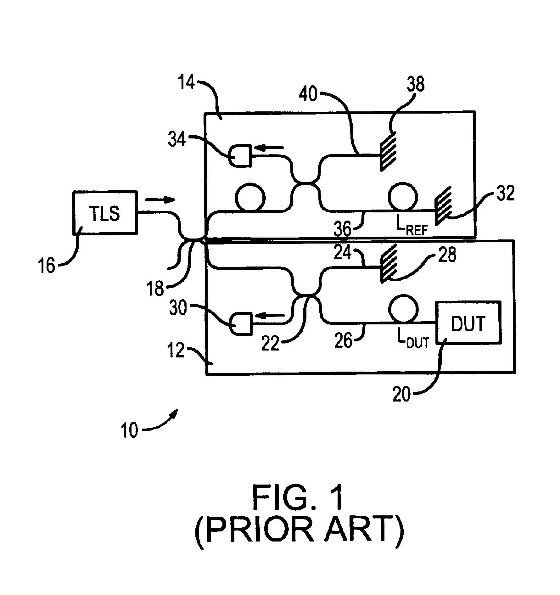
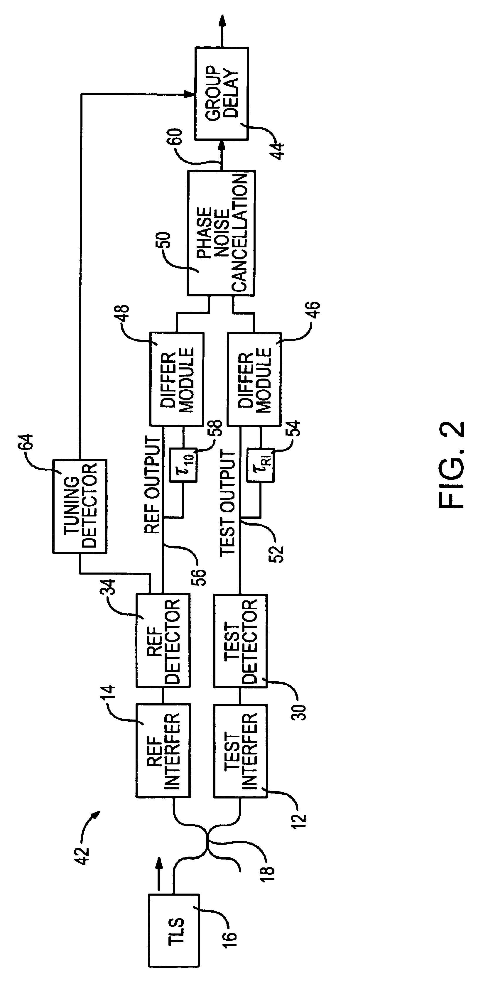
[0015]With reference to FIG. 2, a heterodyne optical network analyzer 42 having phase noise cancellation is shown as being used for measurements of group delay, as indicated by a group delay module 44. However, the analyzer may be used for other measurements relevant to optical characteristics of a device under test (DUT), such as measurements of group velocity, transmissivity, reflectivity and chromatic dispersion. Moreover, the phase noise cancellation may be quantified using the techniques to be described below, but the quantifications may be applied in other systems in which beam portions are separately conducted for comparison purposes.

[0016]The analyzer 42 is shown as including components that are the functional equivalents of components of FIG. 1. The coherent light beam that is generated by the TLS 16 is split by a coupler 18 into beam portions that are separately directed to the test interferometer 12 and the reference interferometer 14. The interferometers 12 and 14 may be...


PUM

PropertyMeasurementUnit
lengthsaaaaaaaaaa
phase noiseaaaaaaaaaa
frequencyaaaaaaaaaa

Abstract

Phase noise is at least partially cancelled for an interferometric system by using a delay / phase cross-correlation approach for two interferometers within the system. The cross-correlation approach may be used in measuring group delay of a device under test and includes determining the differences between the phase of the output of each interferometer at time t and the phase of the same output at the time t minus the delay of the other interferometer. In one embodiment, the first phase difference is the difference between the phase of a test interferometer output at time t and the phase of the test interferometer output at the time t offset by the known delay of a reference interferometer. The second phase difference is calculated using the same technique, but the time offset is a delay representative of the relative delay of two light propagations within the test interferometer. A noise-cancelled time series output that is indicative of group delay can then be generated by determining the difference between the first and second differences.

Description

TECHNICAL FIELD[0001]The invention relates generally to obtaining measurements for optical characteristics of a device under test and more particularly to canceling phase noise from measurements of group delay introduced by the device under test.BACKGROUND ART[0002]Techniques for testing or analyzing optical components are known. A “device” under test (DUT), such as a length of fiber optic cable, may be carefully tested for faults or may be analyzed to determine whether the device is suitable for use in a particular application. System components such as multiplexers, demultiplexers, cross connectors, and devices having fiber Bragg gratings may be separately tested before a system is assembled.[0003]Optical testing may be performed using a heterodyne optical network analyzer. Such analyzers may be employed for measuring properties of optical components, such as group delay. “Group delay” is sometimes referred to as envelope delay, since it refers to the frequency-dependent delay of ...

Claims


Application Information

Patent Timeline
Patent Type & Authority Patents(United States)
IPC IPC(8): G01B9/02
CPCG01B9/02G01B9/02004G01B2290/60
Inventor VAN WIGGEREN, GREGORY D.
Owner AGILENT TECH INC
Learn More