
Miniature sports radar speed measuring device

a speed measuring device and miniature technology, applied in the direction of reradiation, gymnastics exercise, instruments, etc., can solve the problems of system costing several hundred dollars, user disadvantages, and device design or complexity, and achieve the effect of eliminating erroneous readings and optimizing the trajectory of markers

Inactive Publication Date: 2005-05-31
SPORTS SENSORS
View PDF28 Cites 38 Cited by
  • Summary
  • Abstract
  • Description
  • Claims
  • Application Information

AI Technical Summary

Benefits of technology

"The present invention provides a small and low-cost radar speed sensor that can measure the speed of objects, particularly sports equipment, with high accuracy. The sensor is practical for consumer applications, such as recreation and sports, and can be calibrated for different sports and activities. It is designed to be mounted at or near the location where the object is being shot or thrown, and it uses a low power, short range signal that is emitted and reflected back to the sensor. The sensor is easy to use, low in power consumption, and produces accurate speed measurements. The speed measuring device is small and low-cost, making it ideal for recreational and sports applications."

Problems solved by technology

Such methods and systems can produce valid speed measurements, but the cost or complexity of device design, setup and use can present disadvantages to the user.
Further, such systems may cost several hundred dollars.
Implementation of prior art CW Doppler radar systems is relatively complex, generally involving the use of an RF oscillator and signal generator, an antenna system to radiate the oscillator output into free-space and to receive a portion of the transmitted electromagnetic energy that is reflected by the moving object, a transmit / receive switch, diplexer, or circulator device if a single antenna is used for both transmit and receive rather than separate transmit and receive antennas, and various local oscillators, mixers, phase-locked-loops and other front-end circuits to heterodyne, demodulate and detect the Doppler signal.
This complexity imposes high cost and size requirements on the radar units, which have heretofore discouraged the utilization of CW Doppler technology in consumer applications where extremely small size and low cost are necessary for practical end product realization.
Such homodyne circuits are but among hundreds or thousands of circuits and modulation schemes that in some way carry speed information but which have not been considered practical for providing speed measurements.
Accordingly, circuits of a size or cost that are practical for consumer applications such as sports object speed measurement have not been known or available.
Existing Doppler speed measuring devices suffer from loss of accuracy due to the inability to place the unit in or close to the path of the moving object, resulting in a reduction in the speed measurement to the cosine of the angle between the object's velocity vector and the line of the Doppler signal between the unit and the moving object.

Method used


Image

  • Miniature sports radar speed measuring device
  • Miniature sports radar speed measuring device
  • Miniature sports radar speed measuring device

Examples


Embodiment Construction

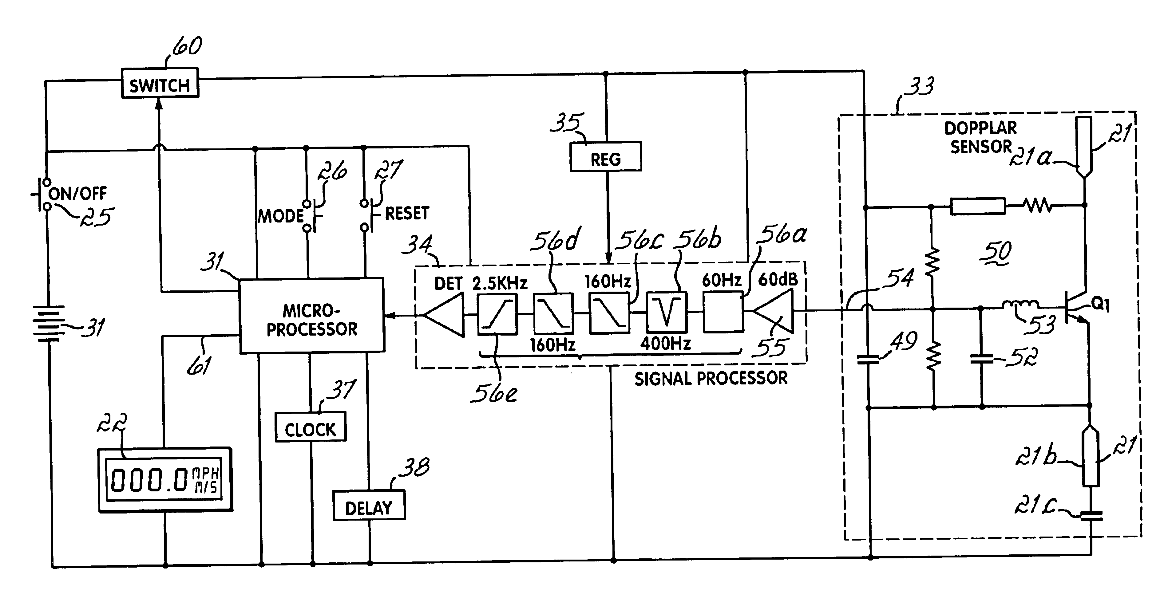
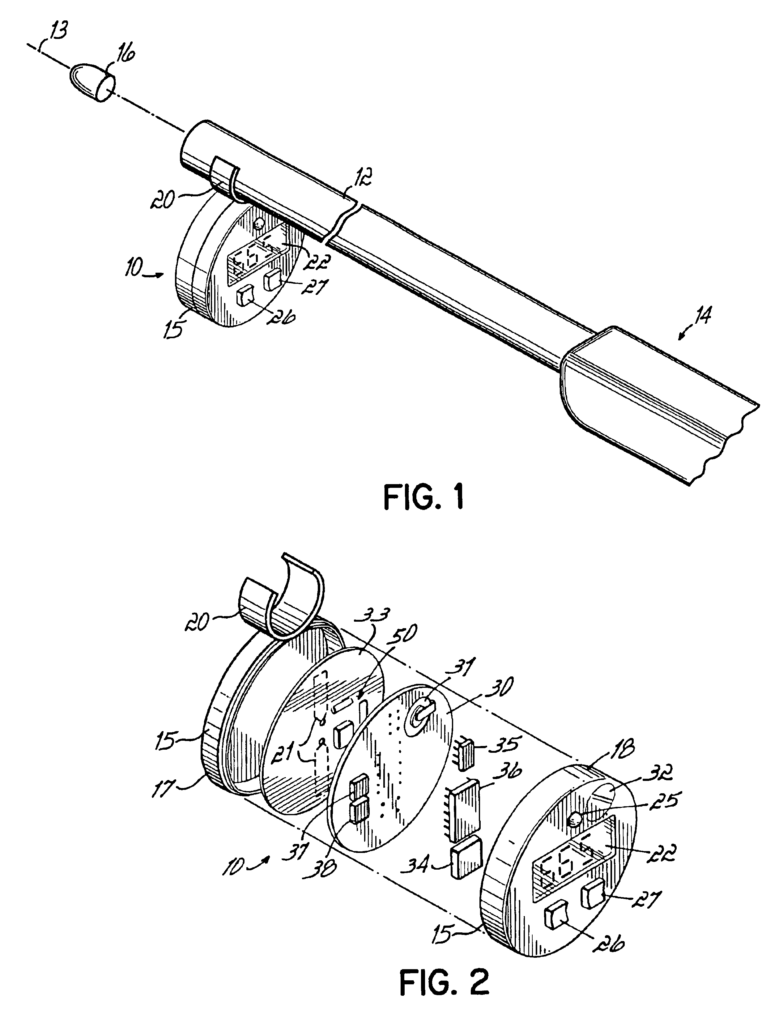
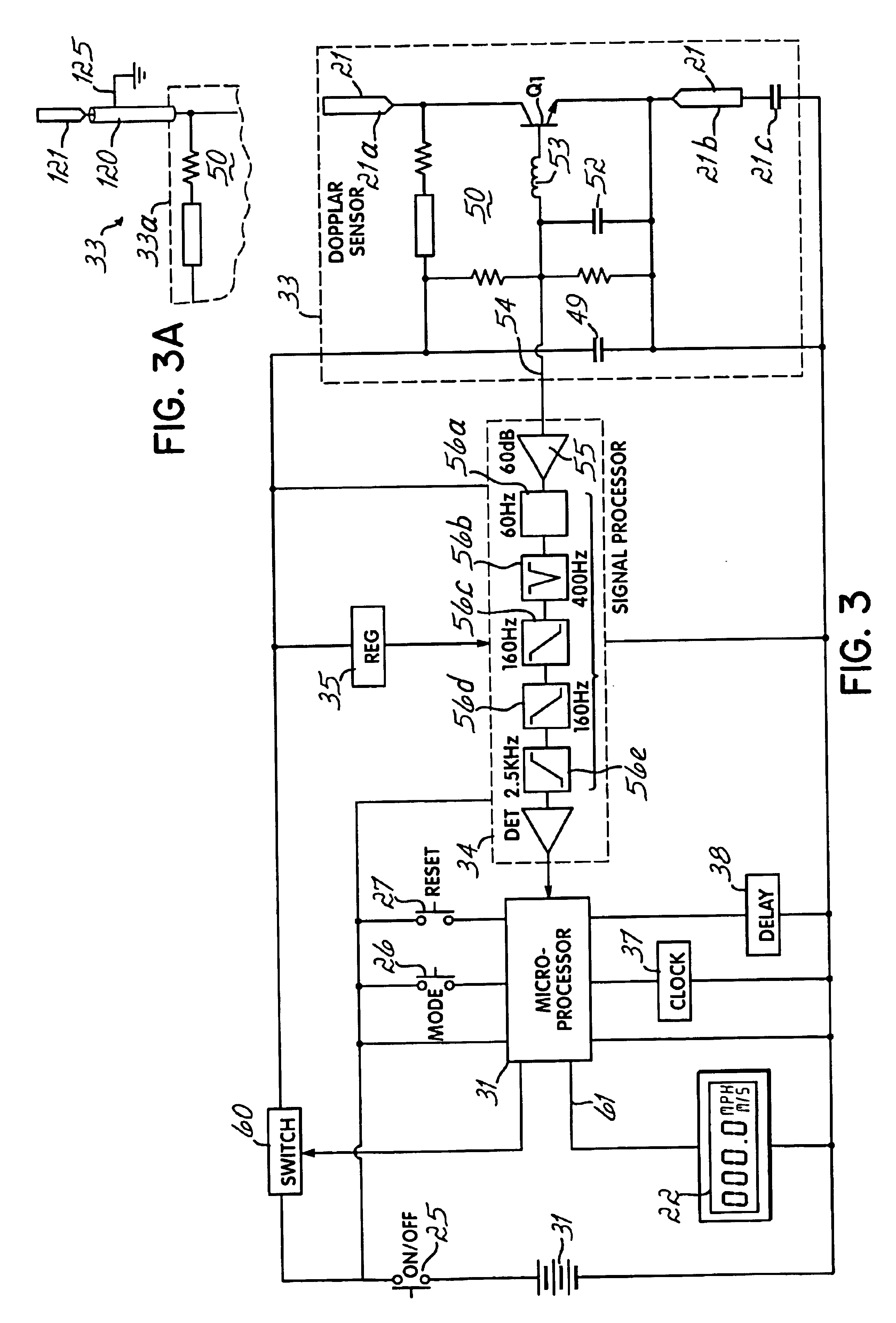
[0042]FIG. 1 illustrates one embodiment of a speed measuring device or unit 10, according to principles of the present invention, secured to the barrel 12 of a rifle or other firearm 14. The firearm 14 is illustrated immediately after having fired a bullet 16 from its barrel 12. The path of the bullet 16 is illustrated by line 13. The device 10, so secured to the barrel 12, is located within a few inches of the direct path 18 of movement of the bullet 16 being fired from the gun 14. The device 10, in the illustrated embodiment, has a two part plastic housing 15 that includes a forward facing housing 17 and a rearward facing housing 18, as illustrated in FIG. 2. In the illustrated embodiment of the unit 10, the two parts of the housing 17,18 are secured together to form a single enclosure that contains the electronics of the unit 10. The forward facing housing 17 is secured by a fastening element or bracket 20, for example, configured or configurable to attach to the barrel 12 of the...


PUM


Abstract

A sensor is provided for measuring the speed of a moving sport object, for example, from a gun, bow or other implement, such as a bullet or paint ball or arrow. The sensor is operable over a short range and is preferably mounted in close proximity to the path of the moving object preferably utilizes CW Doppler radar of a microwave radio frequency. In use, the unit is situated so as to place a transmit / receive antenna close to or in the line of motion of the object. Such an antenna, so positioned, may be separated from the unit and connected through a transmission line. The remote display / annunciator can also or in the alternative be separated and located remote from the transmitter / receiver and connected by a cable or a wireless link. The sensor is useful for other speed measurements in sports applications, such as for measurement of bat speed, golf club head speed or the speed of another racket, club or bat type implement, or to measure punch or kick speed in martial arts.

Description

MINIATURE SPORTS RADAR SPEED MEASURING DEVICE[0001]This application is a Continuation of U.S. patent application Ser. No. 10 / 005,708, filed Dec. 3, 2001, which will issue as U.S. Pat. No. 6,666,089 on Dec. 23, 2003, which is a Continuation-In-Part of International Application No. PCT / US01 / 12535, filed Apr. 17, 2001, hereby expressly incorporated by reference herein, which is a Continuation-In-Part of U.S. patent application Ser. No. 09 / 550,735, filed Apr. 17, 2000, now U.S. Pat. No. 6,378,367, to which priority for this continuation application is claimed, all of which are hereby expressly incorporated by reference herein.[0002]This application is also related to the parent applications of U.S. Pat. No. 6,378,367, which is a Continuation-In-Part of U.S. Pat. No. 6,079,269, which is a Continuation of U.S. Pat. No. 5,864,061; U.S. patent application Ser. No. 09 / 471,905, which is based on U.S. Provisional patent application Ser. No. 60 / 113,378; and U.S. patent application Ser. No. 09 / 4...

Claims


Application Information

Patent Timeline
Patent Type & Authority Patents(United States)
IPC IPC(8): A63B71/06G01S13/58G01S7/03G01S13/00G01S7/02G01S7/35A63B24/00A63B43/00A63B69/00A63B69/36A63B69/38A63B71/00A63B71/14G01S7/04G01S13/88
CPCA63B24/0021A63B71/00A63B71/06A63B71/14F41B5/14F41C27/00G01S7/032G01S7/35G01S7/352G01S13/583G01S13/88A63B69/0002A63B69/004A63B69/3632A63B69/38A63B71/0605A63B2024/0034A63B2220/17A63B2220/40A63B2220/53A63B2225/50A63B2243/0004G01S7/04A63B43/00A63B2102/18A63B2102/182A63B60/46
Inventor DILZ, JR., ALBERT E.
Owner SPORTS SENSORS
Learn More