Vehicle air-conditioning system

Active Publication Date: 2005-05-31
DENSO CORP
View PDF12 Cites 9 Cited by
  • Summary
  • Abstract
  • Description
  • Claims
  • Application Information

AI Technical Summary

Benefits of technology

[0012]The present invention was developed in view of the aforementioned problems. It is therefore an object of the present invention to provide a vehicle air-conditioning system of the dual air conditioner type which comprises a front seat air-conditioning unit for air-conditioning the front seat side in the passenger compartment and a rear seat air-conditioning unit for air-conditioning the rear seat side in the passenger compartment, with an evaporator of the front seat air-conditioning unit and an evaporator of the rear seat air-conditioning unit being connected in parallel. The air-conditioning system is designed to prevent a significant increase in the temperature of air blown into the rear seat area at a low flow rate of refrigerant when compared with the temperature of air blown into the front seat area.
[0014]According to this aspect of the invention in which the temperature at the rear seat evaporator is higher than that at the front seat evaporator, it is possible to control the discharge flow rate of the refrigerant from the compressor such that the temperature at the rear seat evaporator is equal to the target evaporator temperature. Accordingly, even when the temperature of air blown into the rear seat area is to become higher than the temperature of air blown into the front seat area at a low flow rate of refrigerant, the discharge flow rate of the refrigerant from the compressor can be increased to prevent an increase in the temperature of air blown into the rear seat area.
[0016]This also makes it possible to increase the discharge flow rate of the refrigerant from the compressor and thereby prevent an increase in the temperature of air blown into the rear seat area even when the temperature of air blown into the rear seat area is to increase within a range of a low cooling heat load operation (at a low flow rate of the refrigerant).
[0017]Since the temperature of air blown into the rear seat area would hardly be increased within a range of a high cooling heat load operation (at a high flow rate of refrigerant), no problem would occur even by the discharge flow rate of the refrigerant from the compressor being controlled only in accordance with the temperature at the front seat evaporator. Rather, the discharge flow rate of the refrigerant from the compressor could be controlled only in accordance with the temperature at the front seat evaporator to prevent an increase in the drive power of the compressor caused by an increase in the temperature at the rear seat evaporator.
[0019]This makes it possible to positively prevent the extension of the freezing at the evaporator having the lower temperature of temperatures at the front seat evaporator and the rear seat evaporator.
[0020]According to a fourth aspect of the present invention, by way of example, the compressor can be a variable capacity compressor which can vary its discharge capacity such that the discharge capacity of the variable capacity compressor is varied to thereby change the discharge flow rate of refrigerant.

Problems solved by technology

As a result, it was found that a worsened distribution balance between the refrigerant flow rate for the front seat evaporator and that for the rear seat evaporator led to a lack in refrigerant flow rate of the rear seat evaporator, thereby causing a significant increase in the temperature of air blown into the rear seat area when compared with the front seat area.
This makes a passenger in the rear air-conditioned seat feel less comfortable.
During the power saving control operation, this may result in an extremely reduced flow rate of the refrigerant circulating through the rear seat evaporator, thereby causing the temperature of air blown into the rear seat area to be significantly increased, e.g., by about 8° C. when compared with the front seat area and thus leading to a lack in cooling of the rear seat area.
The study showed that this system also had the problem of the temperature of air blown into the rear seat being significantly increased relative to the temperature of air blown into the front seat at a low flow rate of refrigerant.

Method used


Image

  • Vehicle air-conditioning system
  • Vehicle air-conditioning system
  • Vehicle air-conditioning system

Examples


first embodiment

[0033][First Embodiment]

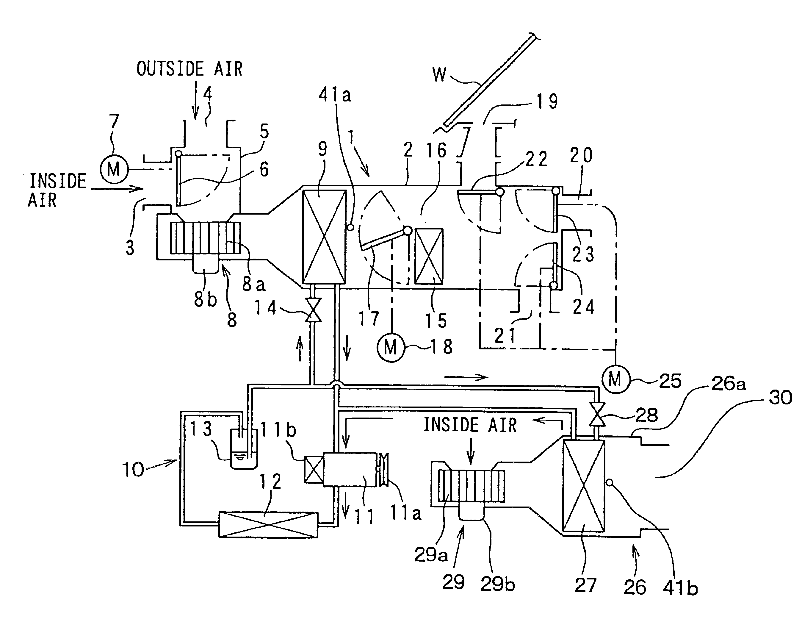
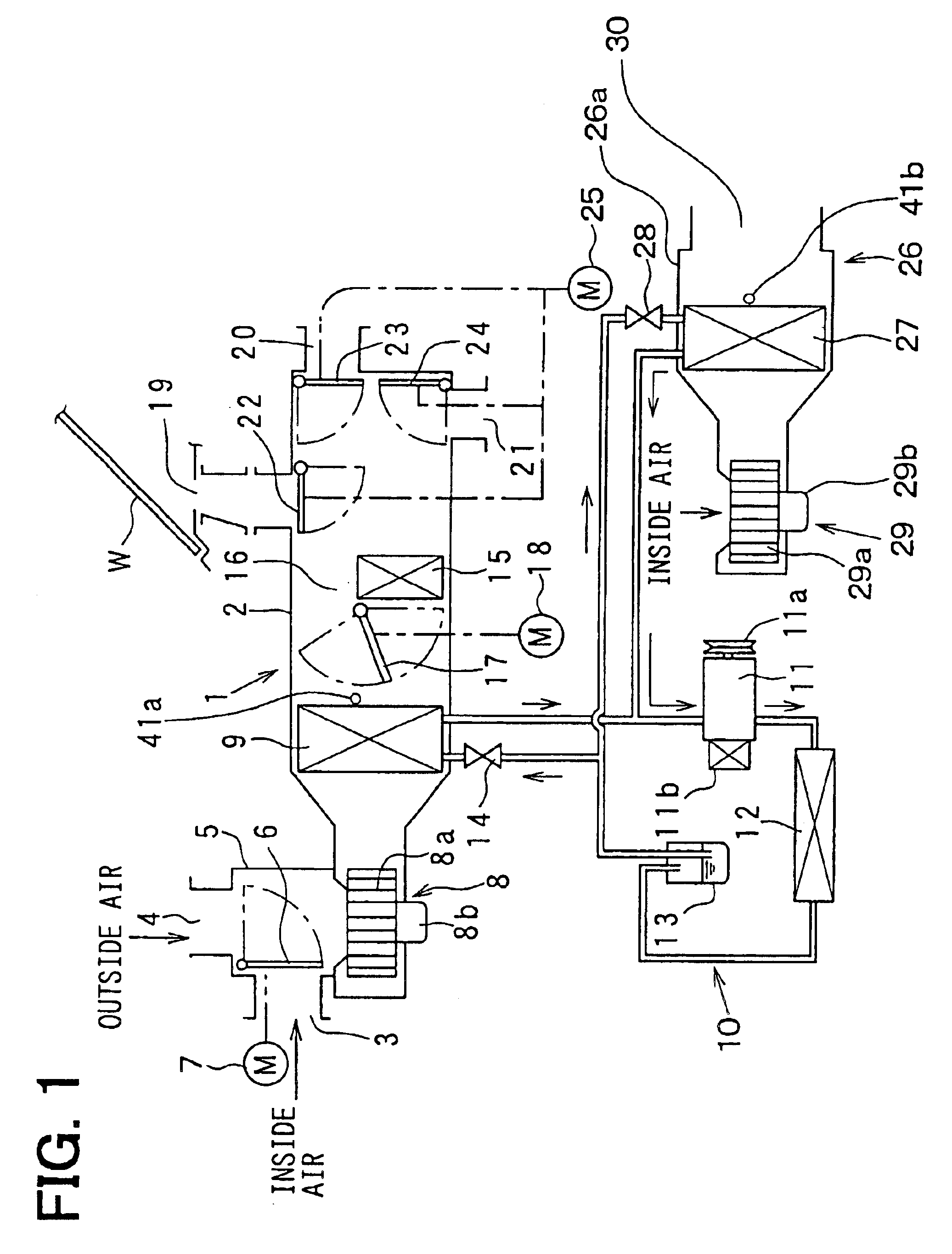
[0034]FIG. 1 is a schematic view illustrating the overall configuration of a vehicle air-conditioning system according to a first embodiment. The air-conditioning system comprises a front seat air-conditioning unit 1 and a rear seat air-conditioning unit 26, which serve as units for air-conditioning a passenger compartment. The front seat air-conditioning unit 1 is disposed behind an instrument panel (not shown) at the front most part of the passenger compartment to air-condition the front seat area in the passenger compartment.

[0035]The front seat air-conditioning unit 1 has a casing 2, in which an air passageway through which air is blown toward the front seat side in the passenger compartment is defined. At the upstream most part of the air passageway in the casing 2, there is disposed an inside / outside air switching box 5 having an inside air inlet port 3 and an outside air inlet port 4. In the inside / outside air switching box 5, an inside / outside air swi...

second embodiment

[0095][Second Embodiment]

[0096]FIG. 6 is a flowchart according to a second embodiment, being different from the flowchart of FIG. 4 according to the first embodiment in that step S180 is added between the steps S120 and S130.

[0097]In step S180, the process determines whether it is within the range of a low cooling heat load operation (i.e., the range of power saving control operation). Here, the cooling heat load depends on the conditions (temperature and humidity) of the air drawn into the evaporators 9, 27, and the conditions of the air drawn are strongly affected by the outside air temperature Tam. Accordingly, for example, the case of the outside air temperature Tam being equal to, or lower than, a predetermined temperature can be determined as within the range of a low cooling heat load operation.

[0098]Within the range of a high cooling heat load operation, the process proceeds from step S180 directly to step S170 in order to provide the regular compressor capacity control and ...

third embodiment

[0102][Third Embodiment]

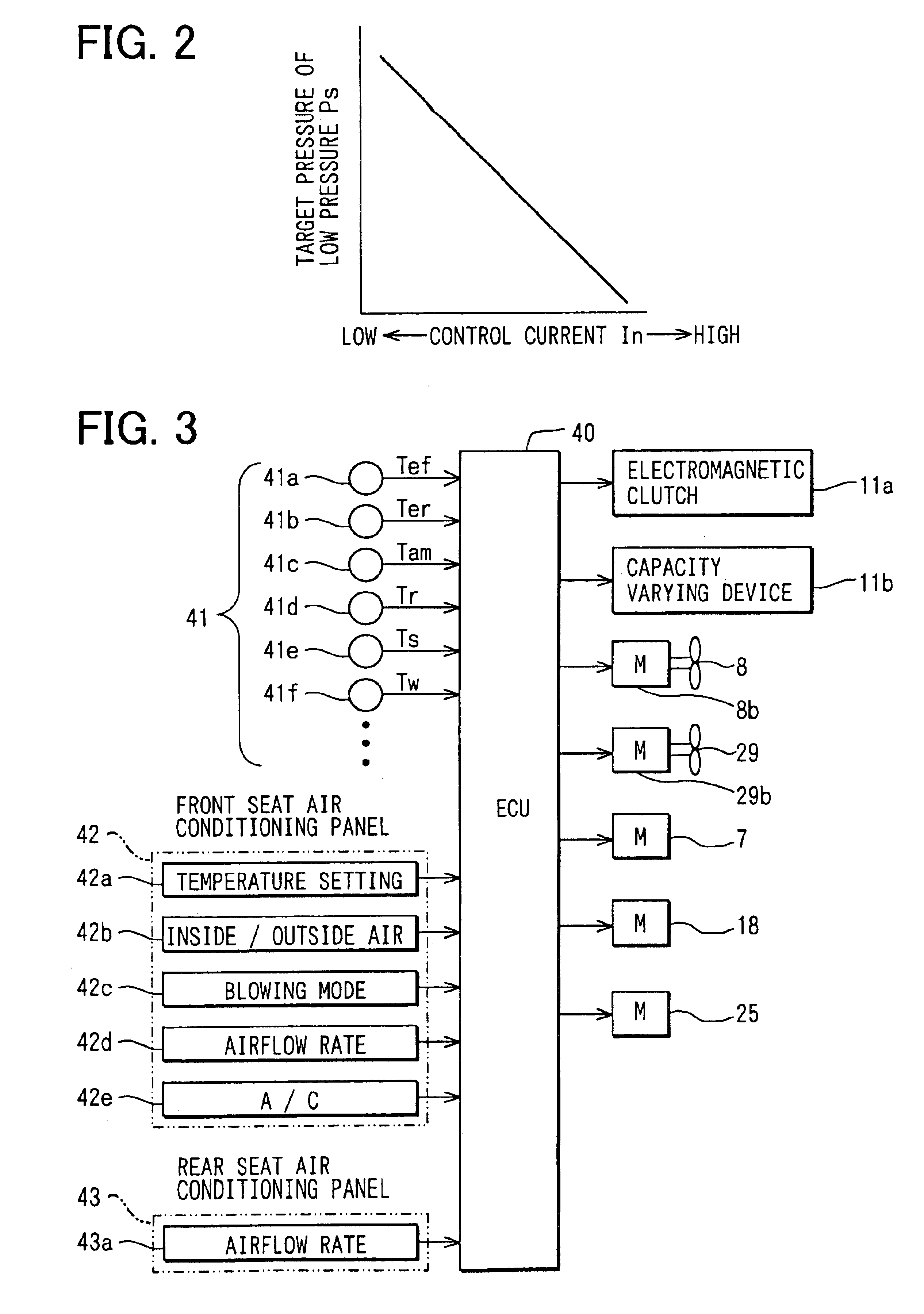
[0103]The first and second embodiments employ a compressor of the low-pressure control type, as the external variable capacity compressor 11, which uses the control current In of the capacity varying device 11b to set a target pressure of the low pressure Ps as shown in FIG. 2 and increases or decreases the discharge capacity so that the low pressure Ps is maintained at the target pressure. However, the third embodiment employs a compressor of the discharge flow rate control type, as the external variable capacity compressor 11, which uses the control current In of the capacity varying device 11b to set a target flow rate Gro of the compressor discharge flow rate as shown in FIG. 7 and increases or decreases the discharge capacity so that the compressor discharge flow rate is maintained at the target flow rate Gro.

[0104]More specifically, the external variable capacity compressor 11 of the discharge flow rate control type according to the third embodiment is ...


PUM


Abstract

A vehicle air-conditioning system of a dual air conditioner type includes a front seat air-conditioning unit for air-conditioning a front seat side and a rear seat air-conditioning unit for air-conditioning a rear seat side. The system includes parallel connected evaporators for the front seat air-conditioning unit and the rear seat air-conditioning unit. At a low flow rate of refrigerant, the system prevents a significant increase in the temperature of air blown into the rear seat area relative to the temperature in the front seat area. The system employs a variable capacity compressor that enables its discharge capacity to be controlled by an external control signal, allowing the discharge capacity of the compressor to be controlled in accordance with the higher evaporator temperature of the temperatures at the front seat evaporator and the rear seat evaporator and a target evaporator temperature.

Description

CROSS REFERENCE TO RELATED APPLICATIONS[0001]This application is based upon, claims the benefit of priority of, and incorporates by reference the contents of, Japanese Patent Application No. 2002-325453 filed on Nov. 8, 2002.FIELD OF THE INVENTION[0002]The present invention relates generally to a vehicle air-conditioning system and, more particularly, to operational control of the vehicle air-conditioning system.BACKGROUND OF THE INVENTION[0003]A conventional vehicle air-conditioning system includes a variable capacity compressor to control the temperature at the evaporator. This system is operative to calculate the deviation of an actual evaporator blowing temperature Te sensed by a temperature sensor from a target evaporator temperature TEO. Next, a capacity control current for the compressor is calculated based upon the above deviation. The capacity control current is delivered to a capacity varying device of the compressor to thereby variably controlling the discharge capacity o...

Claims


Application Information

Patent Timeline
IPC IPC(8): B60H1/32B60H1/00F25B5/02F25B49/02F25B5/00
CPCB60H1/00064B60H1/323F25B5/02F25B49/022B60H2001/00121F25B2700/21173F25B2600/021F25B2600/023F25B2700/2104F25B2700/2106
Inventor OGISO, AKIOYOSHIDA, SATOHISAUMEBAYASHI, MAKOTO
Owner DENSO CORP
Why Eureka
Try Eureka