Assembly supporting device for magnetic tape cartridge

a technology of supporting device and magnetic tape, which is applied in the field of magnetic tape cartridges, can solve the problems that the upper half cannot be properly combined with the lower half,

Inactive Publication Date: 2005-05-31
FUJIFILM CORP
View PDF5 Cites 3 Cited by
  • Summary
  • Abstract
  • Description
  • Claims
  • Application Information

AI Technical Summary

Benefits of technology

[0012]Therefore, it is a first exemplified object of the present invention to provide a magnetic tape cartridge that permits smooth combination of an upper half and lower half of a cartridge case. Moreover, it is a second exemplified object of the present invention to provide an assembly method of a magnetic tape cartridge in which a slide door may be securely mounted using an assembly robot. Further, it is a third exemplified object of the present invention to provide an assembly supportive device that can securely guide a distal end of a spring support rod for a slide door onto a support rod receiving block in a lower half of a cartridge case, so that the assembly operation of the slide door using the assembly robot may be securely performed.
[0014]When the magnetic tape cartridge according to the present invention is assembled, first, each component such as a reel and a safety lug is mounted respectively in a predetermined position of the lower half. Next, a spring member is mounted in the lower half, and thereafter the slide door is fitted into a guide groove in the lower half formed along the inside of the sidewall provided with the opening. At this stage, the slide door is constantly stressed by the action of the spring member toward a direction in which the slide door moves to close the opening, and the front end is kept in contact with an inner edge of the opening that is provided in the sidewall of the lower half to draw out a magnetic tape. According to the magnetic tape cartridge in this first aspect of the present invention, the sidewall includes the holding concave portion, and thus the front end of the slide door may be held in the holding concave portion when the opening is closed with the slide door. Therefore, the slide door is supported with the holding concave portion and prevented from falling in a direction perpendicular to the face of the slide door. Further, disadvantageous circumstances may be avoided in which the slide door could not be neatly fitted into the guide groove in the upper or lower half and thus the upper half could not be properly combined with the lower half.
[0016]According to this method in the second aspect of the present invention, after the lower edge of the slide door is fitted into the guide portion of the lower half, the end of the slide door facing the direction in which the slide door moves to close the opening is held with the chuck device to keep a position of the slide door, and thus the slide door may be kept upright without tilting or falling. Consequently, the lower edge and upper edge of the slide door may be securely fitted respectively into each guide portion in the lower half and the upper half when the lower half and the upper half are combined.
[0017]In the above method of assembling a magnetic cartridge according to the second aspect of the present invention, the end of the slide door facing the direction in which the slide door moves to close the opening may preferably be anchored with a stopper after the upper half is combined with the lower half, and the stopper is removed from the slide door after the slide door is released from the chuck device. This allows the chuck device to be easily and smoothly detached from the front end of the slide door stressed toward the direction in which the slide door moves to close the opening.
[0019]In order to achieve the above second object, a method of assembling a magnetic tape cartridge according to a third exemplified aspect of the present invention comprises the steps of: providing an opening through which a magnetic tape is drawn out in part of a sidewall of a cartridge case across a lower half and an upper half of the cartridge case; mounting a slide door that opens and closes the opening between guide portions each provided in the lower half and the upper half, while stressing the slide door with a spring member toward a position in which the opening is closed. In this method according to the third aspect of the present invention, the above mounting step includes: mounting the slide door stressed with the spring member toward the position in which the opening is closed by fitting a lower edge of the slide door into the guide portion of the lower half; holding the slide door by pressing an appropriate spot of an end of the slide door facing a direction in which the slide door moves to close the opening so that the end of the slide door facing the direction in which the slide door moves to close the opening is prevented from rising out due to stress imposed by the spring member; and combining the upper half with the lower half.
[0020]According to this method in the third aspect of the present invention, after fitting the lower edge of the slide door into the guide portion of the lower half, the slide door is held by pressing an appropriate spot of the end of the slide door facing the direction in which the slide door moves to close the opening, and thus the slide door may be kept upright without tilting or falling. Consequently, the lower edge and upper edge of the slide door may be securely fitted respectively into each guide portion in the lower half and the upper half when the lower half and the upper half are combined.

Problems solved by technology

Further, disadvantageous circumstances may be avoided in which the slide door could not be neatly fitted into the guide groove in the upper or lower half and thus the upper half could not be properly combined with the lower half.

Method used


Image

  • Assembly supporting device for magnetic tape cartridge
  • Assembly supporting device for magnetic tape cartridge
  • Assembly supporting device for magnetic tape cartridge

Examples


first embodiment

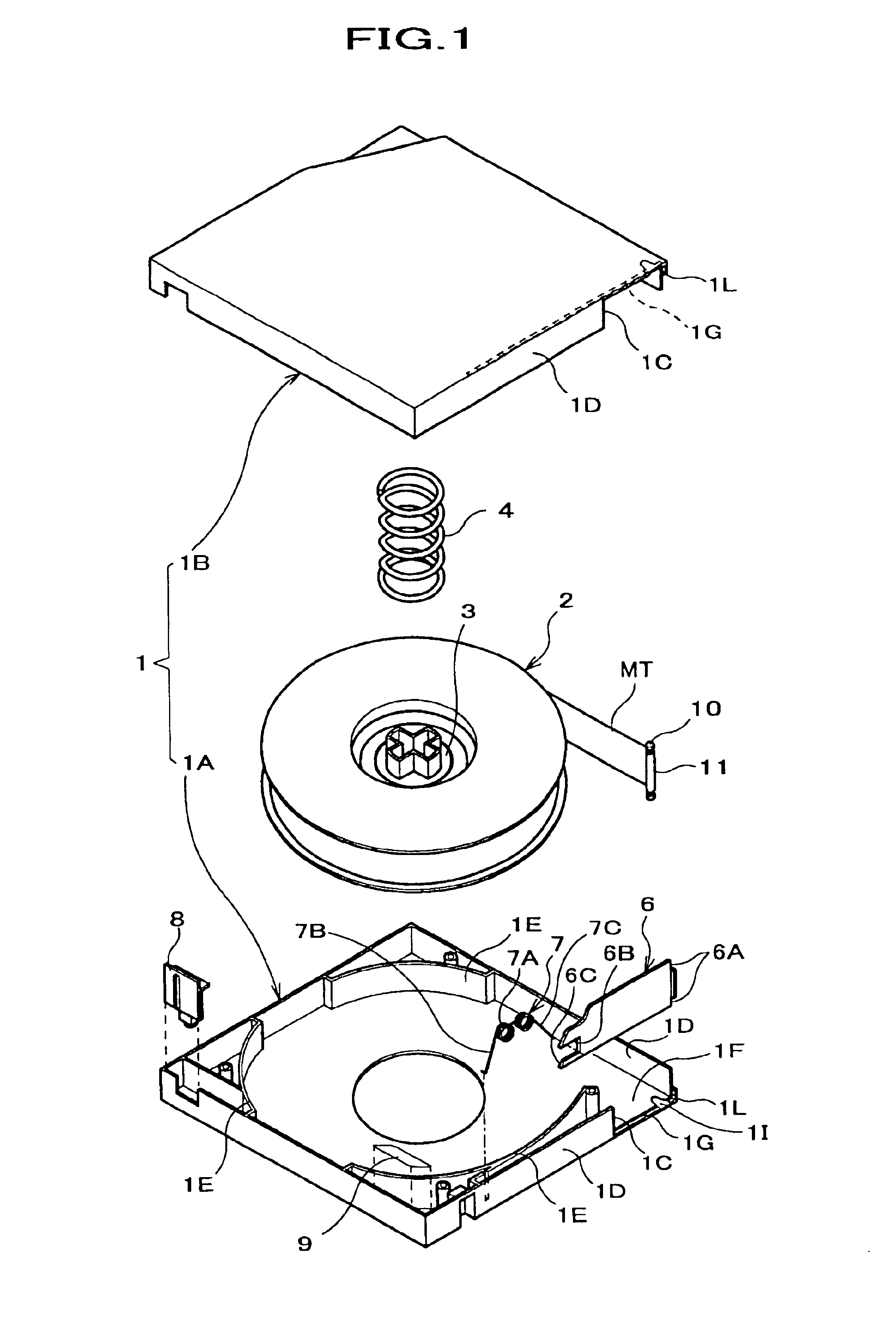
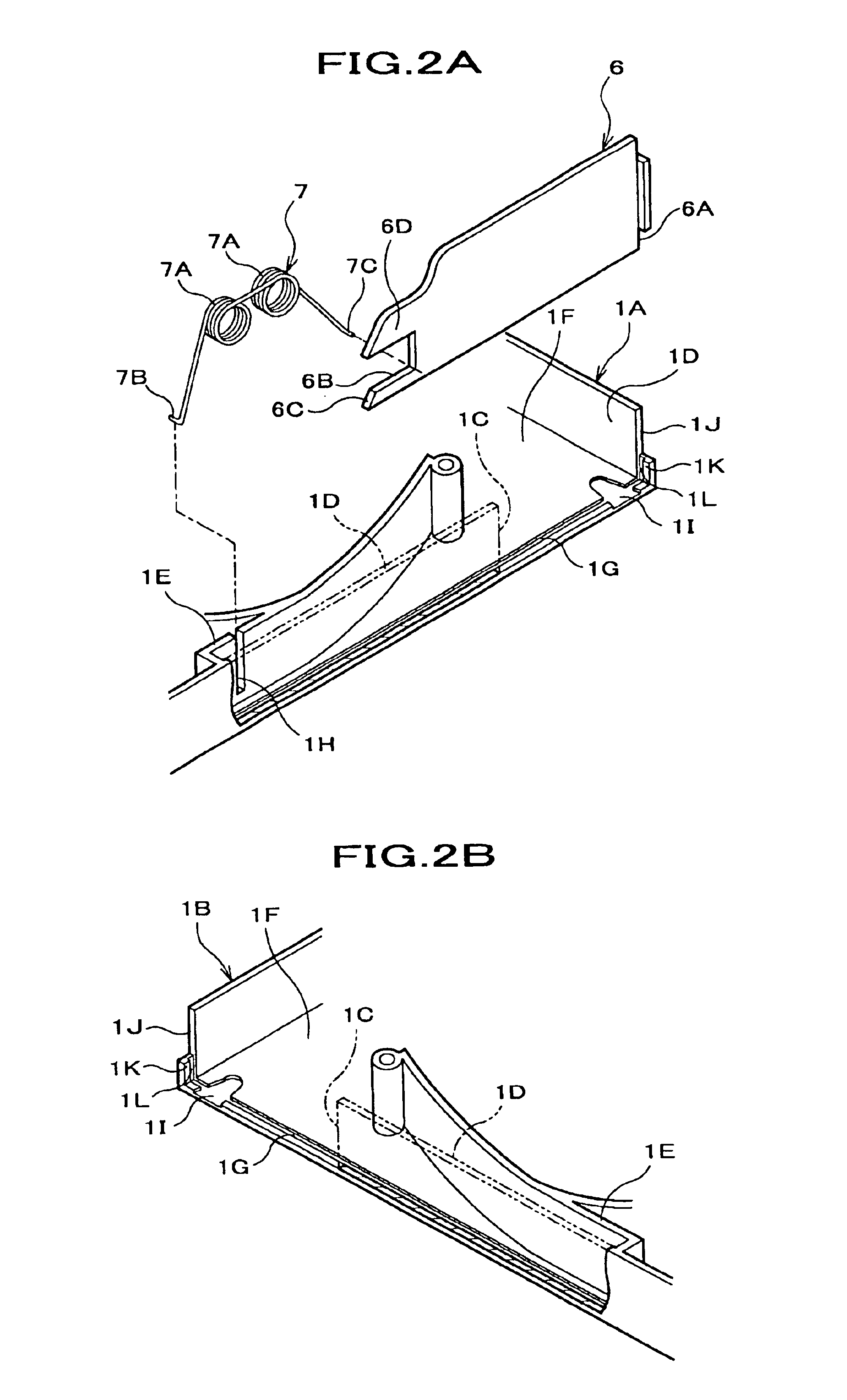
[0055]A description will be given of the preferred embodiments of the present invention with reference to the drawings. First, referring to FIGS. 1 through 6, one exemplified embodiment of a magnetic tape cartridge according to the present invention will be described. The magnetic tape cartridge is comprised of a lower half and an upper half, and an opening through which a magnetic tape is drawn out is provided in a sidewall portion of the cartridge case across the lower half and the upper half. At the sidewall of at least one of the lower half and the upper half is provided a holding concave portion that receives a front end portion of a slide door when the opening is closed. In the drawings, FIG. 1 is an exploded view, in perspective, of components of the magnetic tape cartridge according to the present invention, and FIGS. 2A and 2B are partially magnified perspective views of some components, each depicting a portion around the slide door as shown in FIG. 1.

[0056]The magnetic ta...

second embodiment

[0086]In the method of assembling the magnetic tape cartridge according to the present invention, although the end of the slide door 26 facing the direction in which the slide door 26 moves to close the opening 1C is stopped using the stopper rod S after the lower half 1A and the upper half 1B are combined, the end of the slide door 26 facing the direction in which the slide door 26 moves to close the opening 1C may be stopped using the stopper rod S before the lower half 1A and the upper half 1B are combined, if the end of the slide door 26 facing the direction in which the slide door 26 moves to close the opening 1C has been held by the chuck device CH to keep a posture of the slide door 26.

[0087]Next, a description will be given of a method of assembling a magnetic tape cartridge according to a third embodiment of the present invention with reference to FIGS. 12 through 16. In this method, a lower edge of the slide door is fitted into a guide portion of the lower half, and therea...

fourth embodiment

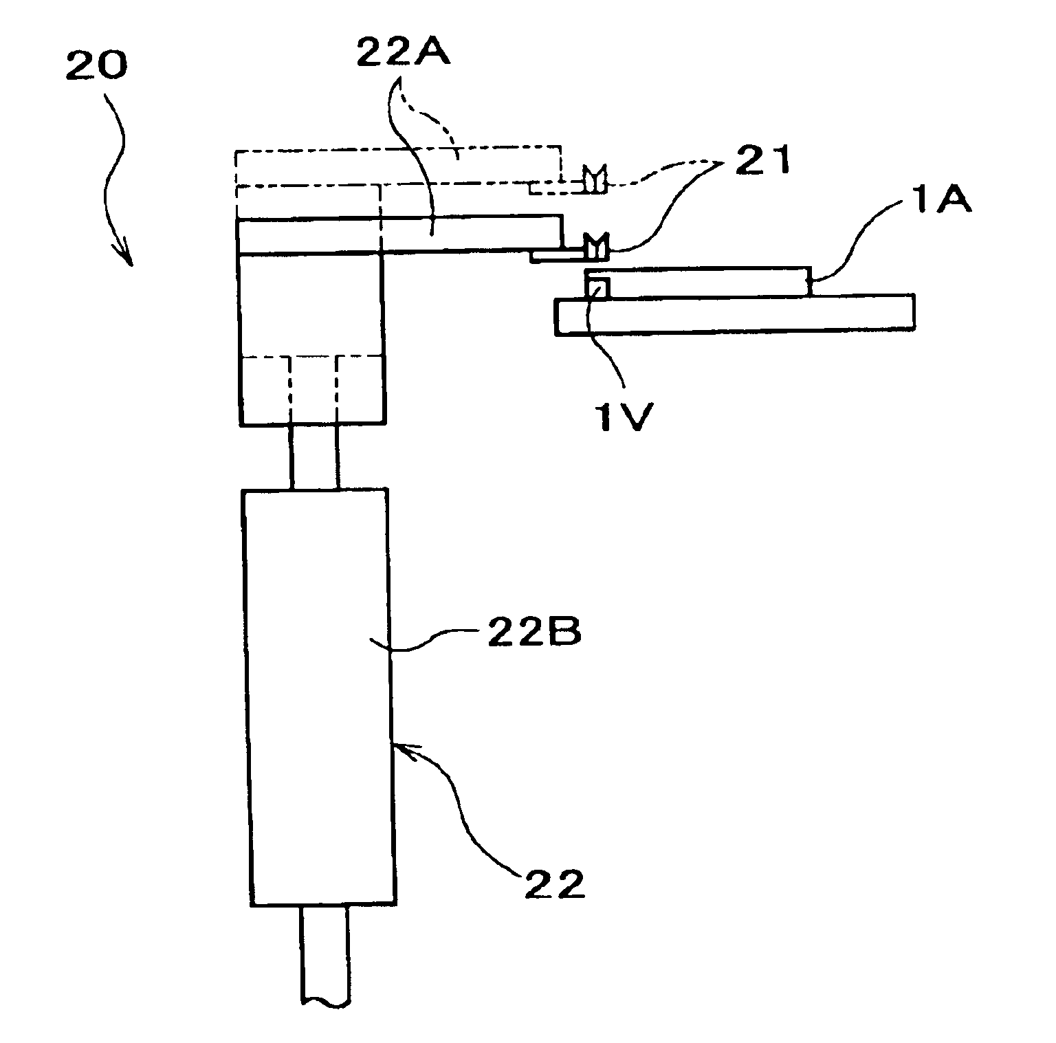
[0107]Next, a description will be given of an operation of fitting the slide door 36 into the lower half 1A shown in FIG. 12 using the assembly supportive device 20 for a magnetic tape cartridge according to the present invention. First, prior to the operation of fitting the slide door 36, all internal components except the slide door 36 and the compression coil spring 37 are mounted each in a predetermined location in the lower half 1A. The internal components include a reel 2, a lock plate 3, a compression coil spring (reel spring) 4, a safety lug 8, a cartridge memory chip 9, and the like. The compression coil spring 37 is wound up around the spring support rod 36B of the slide door 36 in advance, and secured so as not to come off using the stopper head 36C. The assembly operation may be performed manually, but a dedicated assembly device (not shown) or a general-purpose assembly robot may be used, as well.

[0108]When the slide door 36 is mounted in the lower half 1A, the assembly...


PUM

PropertyMeasurementUnit
magneticaaaaaaaaaa
stressaaaaaaaaaa
diameteraaaaaaaaaa

Abstract

A magnetic tape cartridge includes an opening 1C through which a magnetic tape is drawn out, and a slide door 6 that slides along a sidewall 1D provided with the opening 1C to open and close the opening 1C. The cartridge having an assembly support device that guides a distal end of a spring support rod onto a support rod receiving block when the slide door is fitted in a lower half of the cartridge case. A proximal end of the spring support rod projects from the slide door, and a compression coil spring is wound around the spring support rod.

Description

[0001]This is a divisional of application Ser. No. 10 / 158,854 filed Jun. 3, 2002; the disclosure of which is incorporated herein by reference.BACKGROUND OF THE INVENTION[0002]This invention relates to magnetic tape cartridges, and more particularly to a magnetic tape cartridge that permits easy mounting of a slide door openably attached to an opening through which a magnetic tape may be drawn out.[0003]LTO (Linear Tape Open) standard-compliant magnetic tape cartridges have prevailed in the realm of the magnetic tape cartridges used as an external recordable medium for data backup of a computer or the like. The magnetic tape cartridge of this type includes a single reel of magnetic tape and other components in a cartridge case comprised of a lower half and an upper half. At a side of the cartridge case, an opening through which the magnetic tape is drawn out is formed across the lower and upper halves. A slide door shaped like a thin plate for opening / closing the opening is slidably ...

Claims


Application Information

Patent Timeline
Patent Type & Authority Patents(United States)
IPC IPC(8): G11B23/107G11B23/04G11B23/08G11B23/087G11B23/113
CPCG11B23/045G11B23/107Y10T29/49069Y10T29/4984Y10T29/53165Y10T29/49895Y10T29/53465Y10T29/49826Y10T29/49829Y10T29/5313
Inventor YAMAMOTO, HIDETOSHIISHIKAWA, KENJIISHIHARA, YUSUKEOKUTSU, NAOKI
Owner FUJIFILM CORP
Why Eureka
Try Eureka