Rotary support table

Inactive Publication Date: 2005-05-24
VARCO I P INC
View PDF19 Cites 33 Cited by
  • Summary
  • Abstract
  • Description
  • Claims
  • Application Information

AI Technical Summary

Benefits of technology

[0012]In another exemplary embodiment, the rotary seals may be constructed such that the seals further include an outer annular groove formed into the outer seal surface and an inner annular groove formed into the inner seal surface, wherein the plurality of openings are formed between the outer and inner annular grooves, although any shape suitable for forming a fluid tight duct between the seal and the rotary housing may be utilized. Likewise, the seals may be constructed of any material suitable for providing a suitably expandable seal member while providing long-term wear characteristics.
[0013]In another exemplary embodiment, the rotary seal system according to the invention includes an interlock control such that the pressurized fluid is prevented from energizing the rotary seal assembly when the rotary housing is rotating.

Problems solved by technology

This is a time consuming process which requires removal of individual lengths of pipe one at a time in order to completely remove the drill string.
As a result, at each removal or addition of a length of drill pipe from the drill string, oil well personnel are required to exert a great amount of manual physical labor to remove / replace slips, which is dangerous because of the large forces required, as well as the great amount of weight which is being handled.
As such, these devices permanently occupy valuable drill floor space despite the fact that during much of the drill time they will not be in use and may interfere with other drilling operations.
However, in most of the early systems of the rotary power slips, a mechanical linkage had to be provided between a stationary fluid cylinder and the rotary power slip housing.
As a result the assembly protrudes above the rig floor thus consuming valuable space.
However, the expansive seals provided in both of these systems have been found to be prone to leakage and rapid deterioration as a result of rig vibration, affecting the efficacy and alignment of the seal with the rotary housing.
In addition, these prior art devices are prone to introducing mud and debris into the seal and pressurizing system, leading to damage of the hydraulic or pressurized air systems.

Method used


Image

  • Rotary support table
  • Rotary support table
  • Rotary support table

Examples


Embodiment Construction

[0032]The present invention relates to a continuously passively engaged rotary seal for providing fluid communication between a rotary slip bowl and a stationary slip ring.

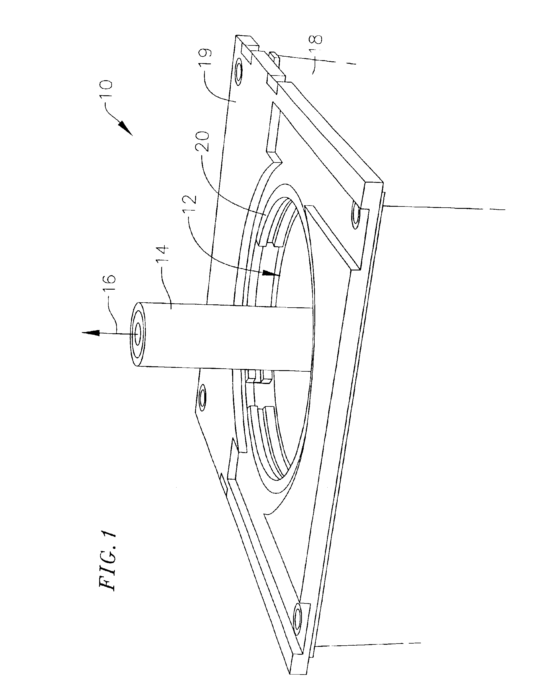
[0033]FIG. 1 depicts an outer perspective view of an exemplary embodiment of the invention including a rotary support table 10 defining a central cylindrical opening or bore 12. The central bore 12 being arranged such that a pipe or drill string 14 can be suspended therein and turned about a vertical axis 16 in the central bore 12. The rotary support table 10 further includes an outer stationary housing 18 having a top cover 19 and a rotary slip bowl 20 disposed within the outer stationary housing 18 and arranged coaxially about the vertical axis 16 of the drill string 14 within the central bore 12. A power slip system (not shown) according to the present invention is disposed within the rotary support table 10.

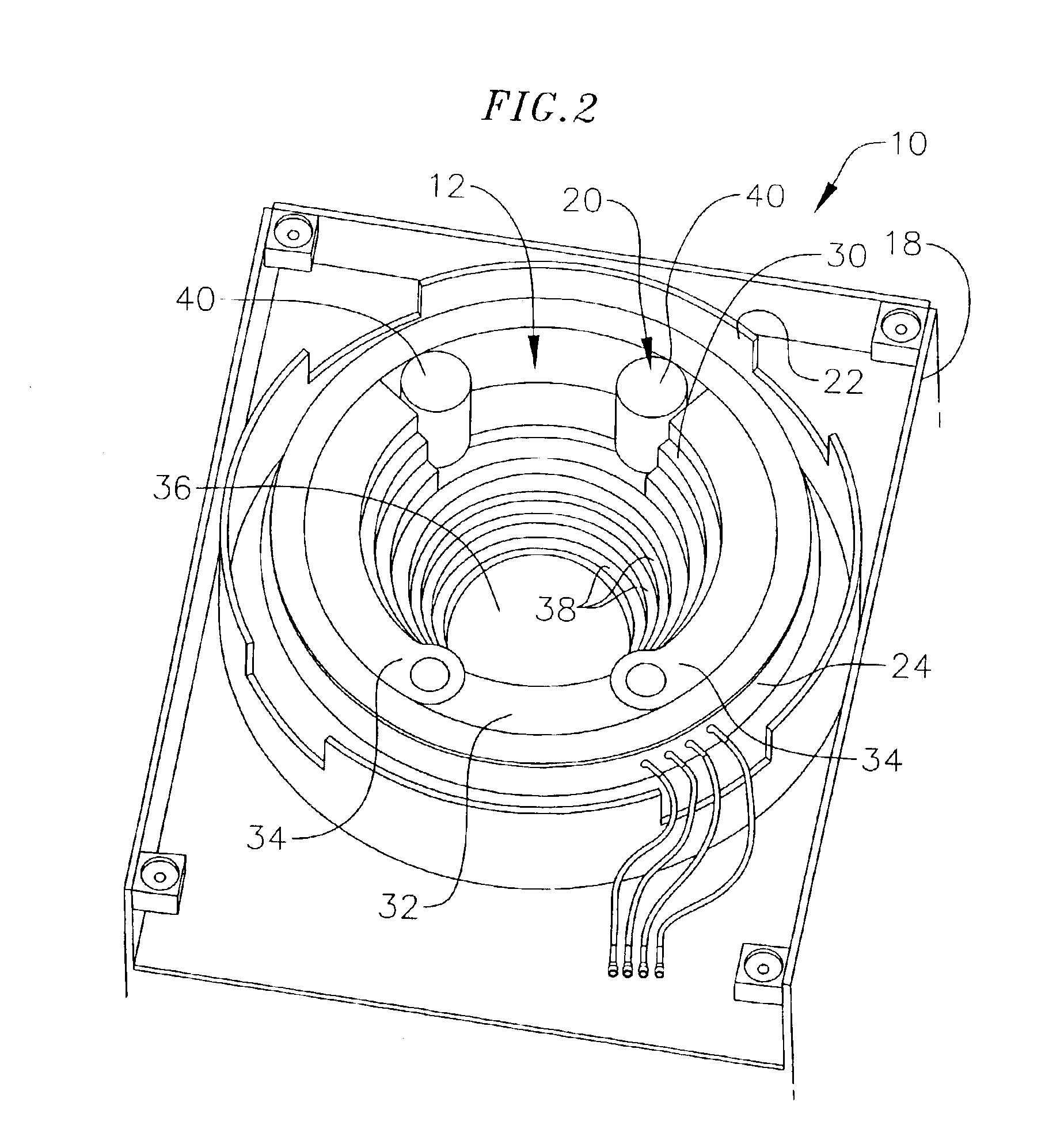
[0034]FIG. 2 depicts a top view of the rotary support table 10 with the top cover removed. As shown, the...


PUM


Abstract

A rotary seal assembly for a rotary support table for use in drilling systems and the like to provide pressurized fluid to a rotary slip assembly disposed within the rotary support table is provided. The rotary seal assembly is designed to be coupled to an existing rotary support table which is used to rotate a drill string, and includes a powered slip that is powered into an engaged position to securely engage a pipe segment, for example, a casing segment. The rotary seal assembly generally comprises a ribbon of expandable material having an outer surface in fluid communication with a source of pressurized fluid, and an inner surface cooperative with a rotary housing, the rotary seal having a plurality of openings capable of communicating fluid between said outer and inner surfaces, wherein the outer seal surface has a surface area greater than the inner surface such that when the pressurized fluid is conducted to the outer surface of the seal a differential pressure between the outer and inner surfaces is created such that the inner surface of the seal is expanded to engage the rotary housing and form an annular fluid duct providing fluid communication between the pressurized fluid source and the rotary housing. A method of operating a rotary table and powered slip assembly utilizing the rotary slip assembly of the current invention is also provided.

Description

CROSS-REFERENCE TO RELATED APPLICATION(S)[0001]This application claims priority under 35 U.S.C. §119(e) to U.S. Provisional Application Ser. No. 60 / 342,998, filed Dec. 21, 2001.FIELD OF THE INVENTION[0002]This invention relates generally to rotary support tables, and more particularly, to a rotary support table having a slip seal arrangement with improved wear and sealing characteristics.BACKGROUND OF THE INVENTION[0003]In most conventional oil or gas drilling operations, drilling takes place on a drilling platform, which in turn supports a circular rotary table. The rotary table is designed such that it can be moved in a circular fashion via standard electrical or hydraulic motors. The conventional rotary table has a “kelly” which provides the central opening or bore through which passes the drill string. The kelly itself is supplied with a bushing or “kelly bushing,” which can be interlocked with a bushing on the rotary table or “master bushing” such that the rotary table can driv...

Claims


Application Information

Patent Timeline
IPC IPC(8): E21B19/00E21B19/08E21B3/04E21B3/00E21BE21B1/00E21B19/10F16J15/18
CPCE21B19/10
Inventor MASON, DAVIDKRIJNEN, ANTONMULDER, RENE
Owner VARCO I P INC
Why Eureka
Try Eureka