
Hydrogen gas indicator system

a technology of hydrogen gas and indicator system, which is applied in the direction of chemical indicators, instruments, specific gravity measurement, etc., can solve the problems of hydrogen safety, fire or explosion, and safety concerns that are particularly difficult to overcome, and achieve the effect of simple, low cost, and portableness

Inactive Publication Date: 2005-05-24
HOAGLAND WILLIAM
View PDF13 Cites 40 Cited by
  • Summary
  • Abstract
  • Description
  • Claims
  • Application Information

AI Technical Summary

Benefits of technology

"The invention is a hydrogen gas indicator that can detect the presence of hydrogen gas and provide a visual indication to people nearby. It is reliable and can be used in various environments, including high and low temperatures. The indicator is simple, low-cost, and portable, and can be used with outwear. The invention also includes separable or peelable substrates and discrete indicia that provide information separate from any changes in the physical or electrical properties of the hydrogen gas sensor."

Problems solved by technology

Concerns about hydrogen safety could be a longstanding and formidable barrier to its early introduction as a fuel in clean, sustainable energy systems.
Such safety concerns are particularly difficult to overcome where there is limited operating experience and few, if any, published codes and standards.
This negative perception affects consumer acceptance, production liability, insurability, permitting requirements, and the establishment of other ordinances and regulations, all of which are required for the widespread introduction of commercial hydrogen gas fuels, products, or systems into the marketplace.
Prominent among these concerns may be the possibility of a fire or explosion resulting from an undetected hydrogen gas leak.
A significant problem with existing hydrogen gas sensor technology can be that it may be too large, too immobile, too complex, or too expensive to introduce into a mass market as a personal hydrogen gas detection or indicator technology.
Mass spectrometers and chromatographs, for example, are extremely sensitive, but are also large, immobile, expensive, require skilled operators, and may have long response times.
Another significant problem with existing hydrogen gas sensor technology can be that it is not practical for continuous monitoring.
Another significant problem with existing hydrogen gas sensor technology can be that the hydrogen sensor can be dangerous to use.
As can be understood, an ignition source can be dangerous when there is a large amount of the combustible material available.
Another significant problem with existing hydrogen gas sensor technology can be that the technology lacks specificity to hydrogen gas.
However, catalytic sensors also combust other gases such as methane as well and may provide false indications of the presence of hydrogen gas.
Ultrasonic leak detectors are not specific to hydrogen gas and cannot differentiate combustible mixtures from non-combustible mixtures of gases.
Another significant problem with existing hydrogen gas sensor technology can be that the technology does not work in certain environments.
Catalytic combustion sensors may not work in atmospheres of inert gas or pure hydrogen and semiconducting oxides may not work in atmospheres of inert gas.
Bubble detection, electrochemical sensors using selectably permeable membranes, or thermal conductivity sensors may not work or may work inconsistently at lower or variable temperatures.
Another significant problem with existing hydrogen gas sensor technology can be that the technology may not provide discrete indicia beyond the change in the physical or electrical properties of the hydrogen gas sensor itself that can be visually, audibly or tactily discerned or observed by persons in the environment surrounding the hydrogen gas sensor.

Method used


Image

  • Hydrogen gas indicator system
  • Hydrogen gas indicator system
  • Hydrogen gas indicator system

Examples


Embodiment Construction

[0028]The invention involves devices, methods, and compositions involving hydrogen gas sensors that can provide discrete indicia of the presence of hydrogen gas separate from any change in the physical properties of the hydrogen gas sensor material itself.

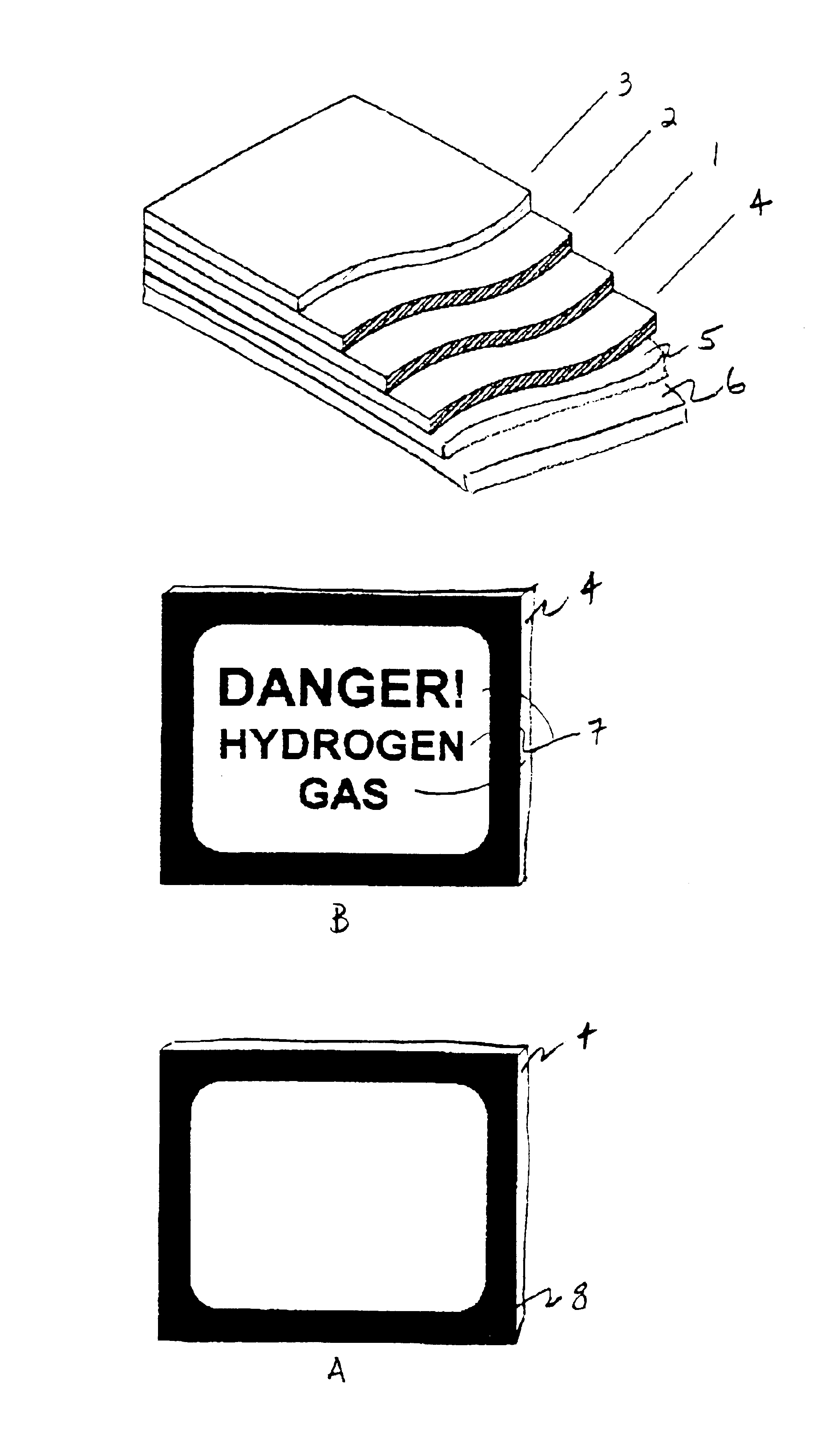
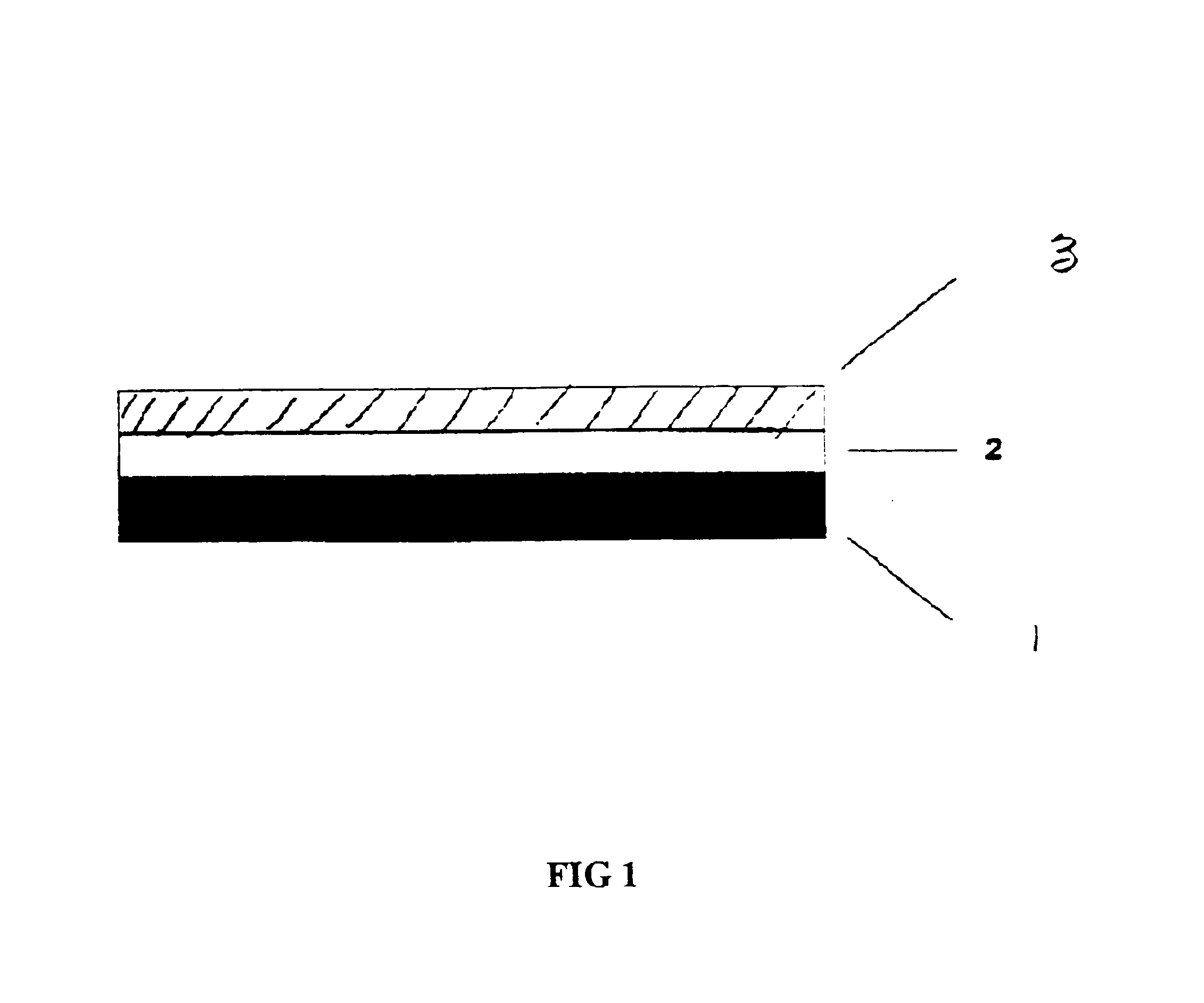
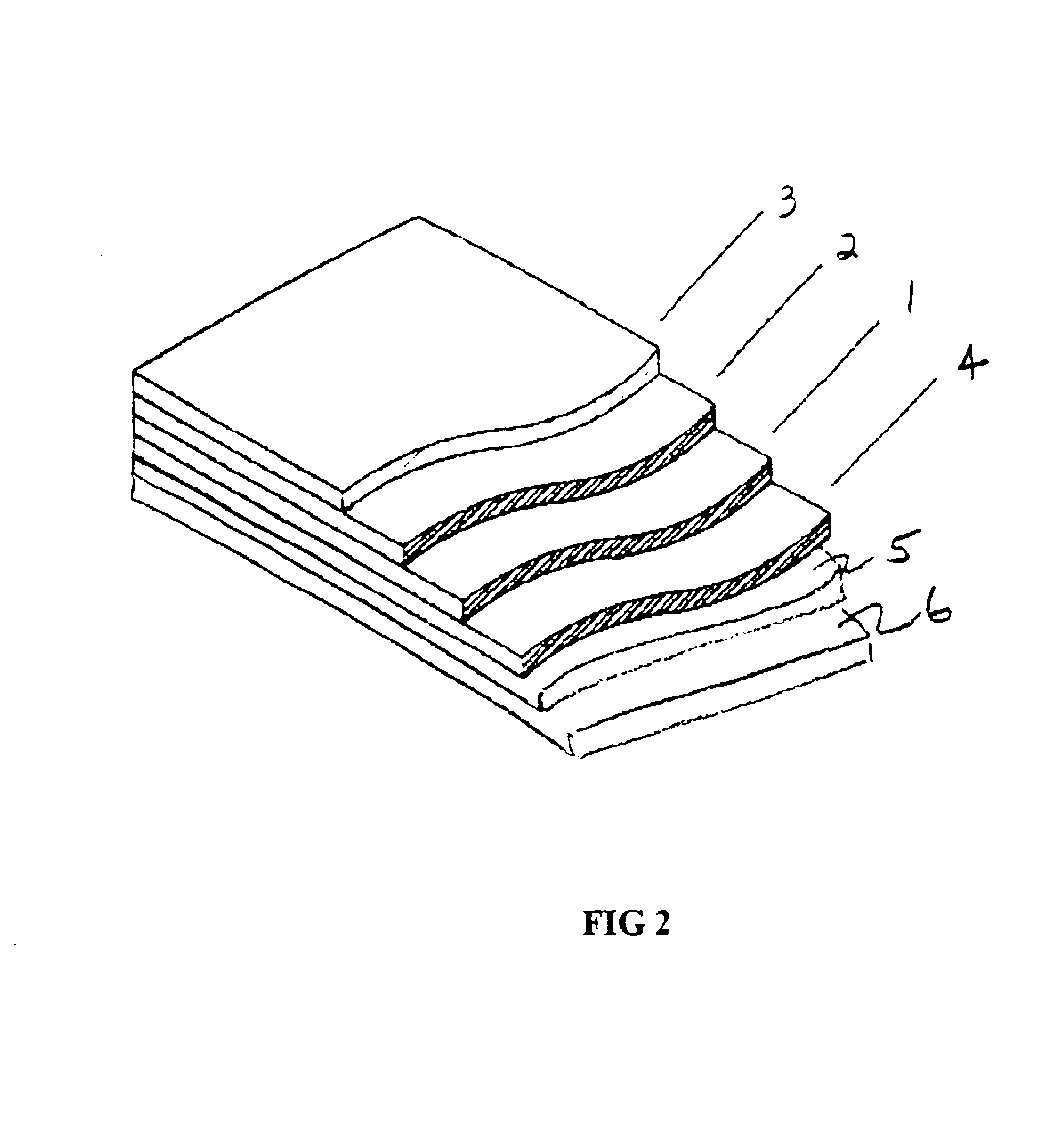
[0029]Now referring primarily to FIG. 1, certain embodiments of the invention can comprise a hydrogen gas indicator comprising three components. The first component can be a hydrogen gas sensor material (1) of transition metal oxides or oxysalt such as vanadium oxide, tungsten oxide, molybdenum oxide, yttrium oxide, or combinations thereof, as examples. When exposed to atomic hydrogen the metal oxide can be reduced to the corresponding metal. The reduction from the metal oxide to the corresponding metal can be accompanied by a change in electrical conduction, electrical resistivity, electrocapacitance, magneto-resistance, photoconductivity, or optical properties of the hydrogen gas sensor (1). The change in such physical properties...


PUM

PropertyMeasurementUnit
thicknessaaaaaaaaaa
thicknessaaaaaaaaaa
friableaaaaaaaaaa

Abstract

A hydrogen gas indicator system that provides various substrate materials (4) that support hydrogen gas sensor (1) materials with discrete indicia (7) that provide information separate from any change in the physical properties of the hydrogen gas sensor itself.

Description

[0001]This application is the United States National Stage of International Application No. PCT / US01 / 47151, filed Dec. 5, 2001, which claims the benefit of U.S. Provisional Patent Application No. 60 / 251,297, filed Dec. 5, 2000, each hereby incorporated by reference herein.[0002]This application claims the benefit of U.S. Provisional Patent Application No. 60 / 251,297, filed Dec. 5, 2000, hereby incorporated by reference.I. TECHNICAL FIELD[0003]A hydrogen gas indicator system that provides indicators of the presence of hydrogen gas in the environment that are discrete from the hydrogen gas sensor material itself.II. BACKGROUND[0004]In the coming decades, hydrogen may be stored and used in new energy systems in vast quantities. Advances in fuel cells and advances to electric vehicles have brought hydrogen gas to the forefront of the various energy candidates to meet our future energy demands. However, there remains a general perception about the safety with respect to the widespread us...

Claims


Application Information

Patent Timeline
Patent Type & Authority Patents(United States)
IPC IPC(8): G01N33/00G01N31/10
CPCG01N21/783G01N31/10G01N33/0013G01N33/005G01N31/22Y10T436/22
Inventor HOAGLAND, WILLIAM
Owner HOAGLAND WILLIAM
Learn More